Isoelectric focusing systems and methods

a technology of isoelectric focusing and focusing system, which is applied in the direction of fluid pressure measurement, liquid/fluent solid measurement, peptide measurement, etc., can solve the problems of reducing the effectiveness of the electric field in establishing the ph gradient, and the resolution is lower than the preparation system, so as to improve the separation from each other, enhance the overall performance of the device, and reduce or prevent the introduction of bubbles

Inactive Publication Date: 2011-03-17
MASSACHUSETTS INST OF TECH
View PDF6 Cites 3 Cited by
  • Summary
  • Abstract
  • Description
  • Claims
  • Application Information

AI Technical Summary

Benefits of technology

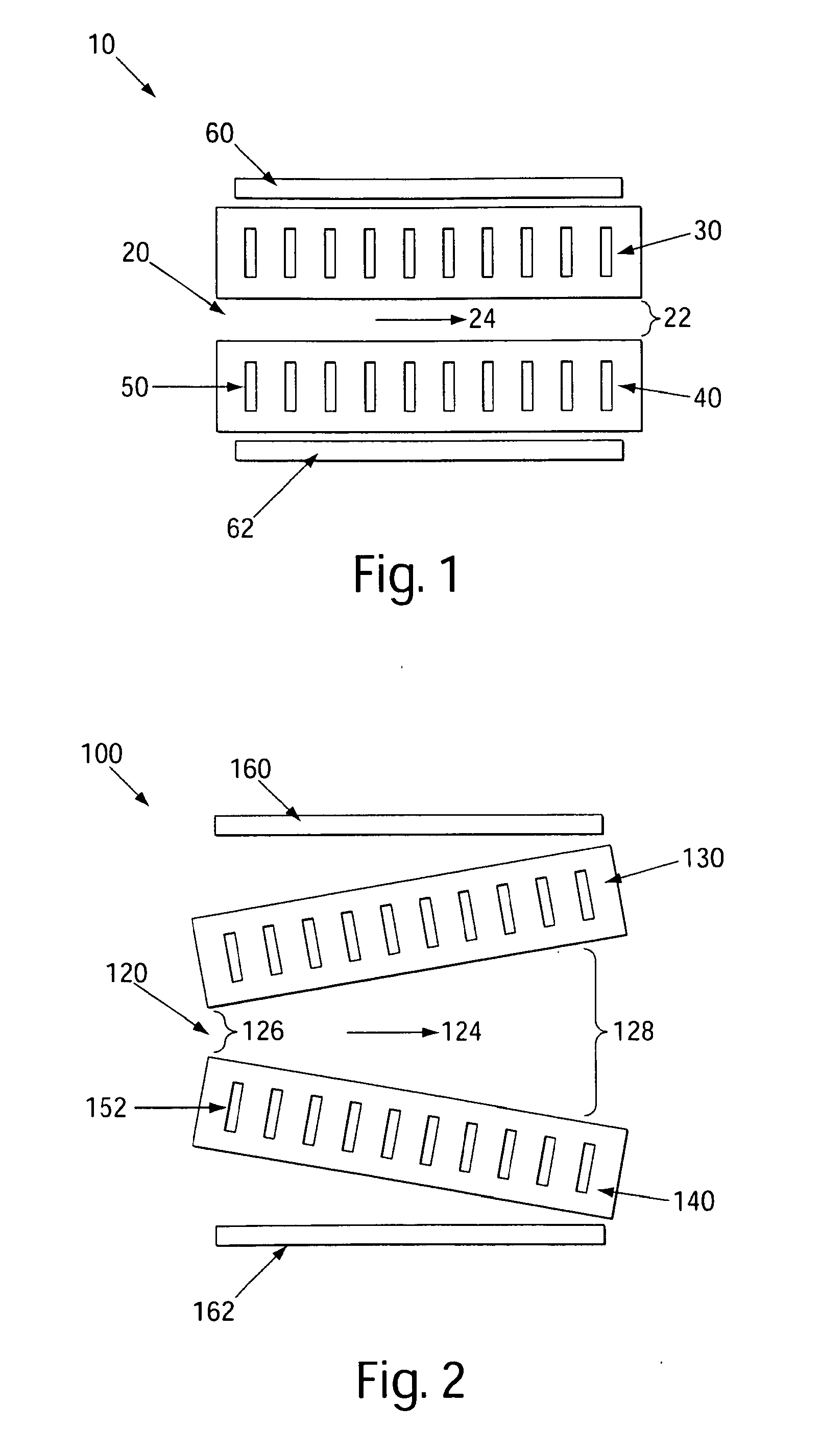
[0026]Some embodiments of the invention involve the use of devices in which a mixture of species can be separated on the basis of the isoelectric points of individual species within the mixture. As used herein, “isoelectric point” is given its ordinary meaning in the art and refers to the pH at which a species is immobilized in an electric field. That is, a pH gradient may be formed in the presence of an electric field such that, species within a mixture, when introduced into the environment comprising the pH gradient, may migrate to a location corresponding to its isoelectric point (pI) where the species has no net charge. Such methods may be useful in the separation of a mixture of proteins, for example. This principle, which is known generally in the art, is illustrated schematically with reference to FIG. 1. As shown in FIG. 1, device 10 may comprise a channel 20 and electrodes 60 and 62, which may be positioned relative to channel 20 such that, upon application of an electric field, a pH gradient may be established in a direction which is perpendicular to the primary direction of fluid flow. A mixture of proteins may be flowed into channel 20 in a direction 24, wherein the proteins are separated in the pH gradient on the basis of isoelectric point.
[0027]The present invention generally involves the discovery that certain variations in the configuration of a FF-IEF device can greatly enhance overall performance of the device. In some cases, the devices may involve variation of, for example, at least one dimension of the channel through which the mixture of species flows. The dimension may include the length, width, height, diameter, shape, and / or other characteristic of at least a portion of the channel. Some embodiments may include variation in the configuration of various components and / or regions of the device. In some cases, the devices may include a different pH gradient within different regions of the device. That is, a mixture flowing through a device may be exposed to at least two or more different pH gradients in succession. The pH gradients may be different with respect to the range of pH units and / or the rate of change of pH units per millimeter of the channel (e.g., along the direction of the pH gradient). For example, a fluid sample flowing through the device may pass through a first region, wherein the fluid sample is exposed to a pH gradient spanning a large number of pH units, and, subsequently, may pass through a second region, wherein the fluid sample, or a portion thereof, is exposed to a pH gradient spanning a small number of pH units.
[0028]An electric field may be applied to at least a portion of the channel to establish the pH gradient in a gradient orientation that is essentially perpendicular to the primary direction of fluid flow within the channel. Typically, the electrodes may be positioned on opposing sides of the channel to establish an electric field therebetween. The electrodes may be also placed on external sides of the channel such that the electrodes do not directly contact the fluid flowing through the channel. This may advantageously reduce or prevent the introduction of bubbles, impurities, or other electrolysis products into the channel.
[0029]In some cases, a fluid sample comprising a mixture of species may be exposed to an electric field and pH gradient in a first region of the channel, wherein various species of the mixture are separated according to their isoelectric point along a direction that is substantially perpendicular to the primary direction of fluid flow. That is, the mixture undergoes a first separation of species to produced a first, resolved fluid sample. The resolved fluid sample may be subsequently exposed to an electric field and pH gradient in a second region of the channel, which may be the same or different than that of the first region, wherein at least a portion of the resolved, fluid sample from the first region is further separated to produce a second, resolved fluid sample wherein the species have improved separation from each other, i.e., the fluid sample is more highly resolved. The exposure of the mixture to multiple regions within the channel, each region having a different ability to affect the position of individual species of the mixture within the channel, may allow for the separation of a mixture of species with greater resolution and, in some cases, with greater speed and efficiency.
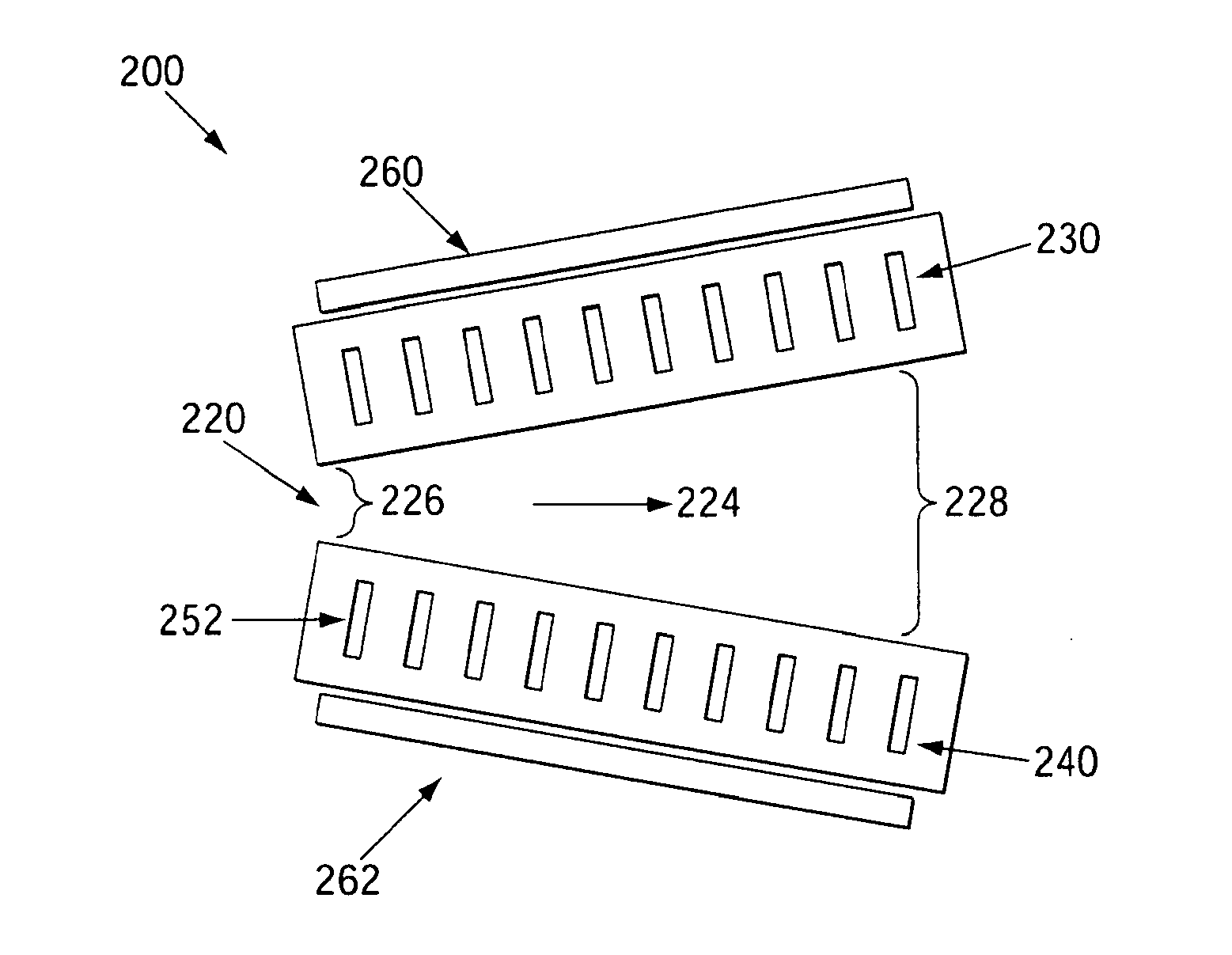
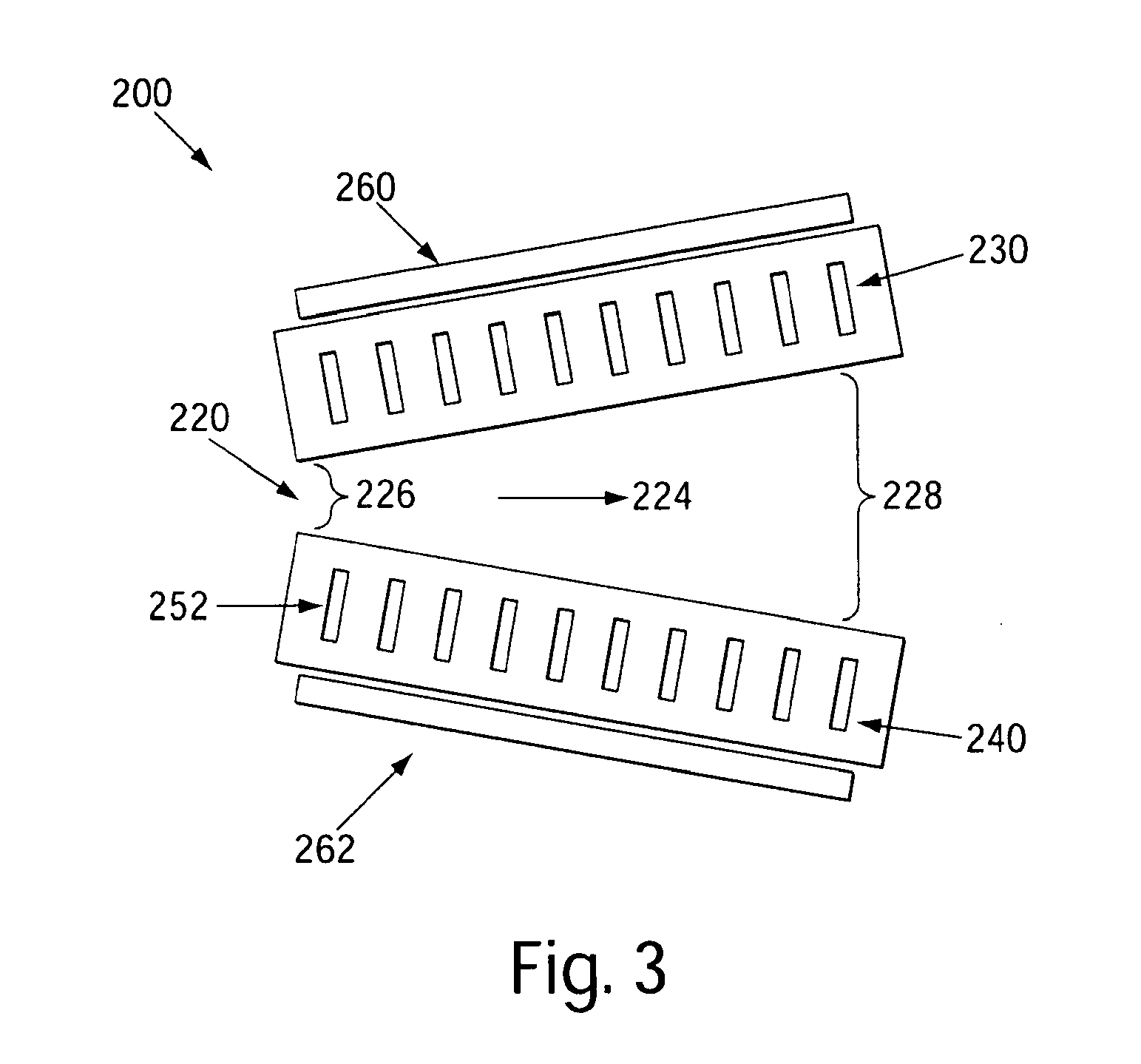
[0030]In some embodiments, the invention provides a device for separating a mixture of species, wherein the device comprises a channel design comprising substantially non-parallel sidewalls, i.e., a “diverging” channel design. The channel may comprise a first portion having a channel width that is less than the channel width of a second portion of the channel. For example, a fluid sample may be introduced into the channel have a narrow width, and, as the fluid sample flows through the channel, the width of the channel may increase. FIG. 2 shows an illustrative embodiment of a device comprising a diverging channel configuration of the invention. As shown in FIG. 2, device 100 comprises a channel 120 through which fluid may flow in a direction 124. The fluid may enter channel 120 and be exposed to a first region 126 having a relatively narrow channel width. The fluid may then flow further downstream and be exposed to a second region 128 having a relatively wide channel width. Region 126 and region 128 may each affect the fluid flowing through channel 120.
[0031]In some cases, the electric field applied to the channel in a first region of the channel may be substantially the same as that applied to the channel in the second region, for example, in a diverging channel configuration. That is, the electrodes may be separated by substantially the same distance and essentially the same voltage may be applied between electrodes at different regions of the channel. For example, two electrodes may be positioned on opposing sides of the channel in a parallel arrangement such that the distance between electrodes and the voltage applied between electrodes may be the same at any location in the channel between the two electrodes. As shown in FIG. 2, device 100 comprises electrodes 160 and 162 positioned parallel with respect to one another, forming an electric field in an orientation perpendicular to the primary direction of fluid flow within channel 120. As a result, the electric field in region 126 of the channel may be essentially the same as that in region 128 of the channel.

Problems solved by technology

Generally, in such cases, the distance between electrodes on either side of the channel may reduce the effectiveness of the electric field in establishing the pH gradient, and the pH gradient must be artificially established by the introduction of pH buffers into the channel.
Such devices have been shown to effectively separate and concentrate species, such as fluorescent dyes, proteins and organelles, but often with lower resolution when compared to preparative systems.

Method used


Image

  • Isoelectric focusing systems and methods
  • Isoelectric focusing systems and methods
  • Isoelectric focusing systems and methods

Examples


example 1

[0059]The following example describes the theoretical Basis for IEF, according to an illustrative embodiment of the invention. Mass transport equations were used as the starting point to formulate expressions to describe isoelectric focusing. The conservation equation for species in solution experiencing an electrophoretic force is given by Equation (1), below:

∂Ci∂t=∇_·(Di∇_·Ci-E_ziωiCi)(1)

[0060]In Equation (1) the concentration of a species C, is a function of position and time, electric field E, variable charge zi, constant mobility μi and its diffusion constant Di. In order to understand the effect of geometry and physical parameters on focusing, it may be helpful to non-dimensionalize the conservation equation for one-dimensional transient focusing and make two assumptions: i) a linear pH gradient is established over the total width, w, and ii) the species has a linear charge behavior in the channel (dzi / dx=Δzi / L=constant). Non-dimensionalizing and expanding the derivative resul...

example 2

[0067]The model described in Example 1 was used to simulate the focusing of a protein, BSA, in a channel either 1 or 3 mm long. FIG. 8 shows the simulated focusing of BSA under three different geometry configurations at identical field strengths: (a) 1 mm, (b) 3 mm, and (c) 1 mm followed by focusing at 3 mm. To better quantify focusing, the simulation used low electric fields (5 V / cm for each case) for slow, low resolution focusing. The resolution (from a Gaussian fit, R2>0.999) of the focusing was 1.6 times greater for the longer channel. Transitioning from a shorter to a longer channel reached this higher-resolution steady state in 40% less time than the 3 mm case. These results show that the simulation results for small amphoteric molecules may also be applicable to large proteins with complicated electrophoretic behavior.

example 3

[0068]Free flow IEF devices were designed to have a sample channel defined by a porous material capable of allowing ion conduction between the sample channel and the electrode buffer, while preventing fluid convection between the two regions. In this study, a single stage straight channel design 20 mm long by 1 mm wide was compared with a similar straight channel design that was a 30 mm long by 3 mm wide straight channel and a tandem design, as shown in FIG. 9A. The tandem design consisted of four focusing regions: the first IEF stage is a single channel (1 mm wide by 7.62 mm long) that branches into three secondary IEF stages with dimensions identical to the first stage. A split configuration may provide i) a more uniform fluidic resistance for an improved flow field and sample collection, as well as a higher degree of control over the electric field within the device. The designs were based on a PDMS channel bordered by posts to define placement of the porous material without the ...


PUM

PropertyMeasurementUnit
particle sizeaaaaaaaaaa
lengthaaaaaaaaaa
lengthaaaaaaaaaa

Abstract

The invention relates to devices and methods for the separation of species, including biological species and involves the use of free flow isolectric focusing (FF-IEF) devices capable of establishing a pH gradient in a gradient orientation that is perpendicular to the direction of fluid flow. In one embodiment a channel (224) constructed and arranged to receive a fluid flow, comprises non-parallel sidewalls (230, 240) and at least two electrodes (260,262). In a further embodiment the device comprises a first region comprising a first channel and a second region comprising at least two channels fluidly connected to the first channel. A method is also disclosed wherein a channel is provided, the channel comprising a first region and a second region, wherein the first region has a first pH gradient across the channel in a gradient orientation that is perpendicular to the direction of fluid flow and the second region has a second pH gradient across the channel in a gradient orientation that is perpendicular to the direction of fluid flow.

Description

STATEMENT REGARDING FEDERALLY SPONSORED RESEARCH OR DEVELOPMENT[0001]This invention was made with the support under the following government contract: P50-GM68762 awarded by the National Institute of Health. The government has certain rights in the invention.FIELD OF THE INVENTION[0002]The present invention generally relates to devices and methods for the separation of species, including biological species.BACKGROUND OF THE INVENTION[0003]Free flow isoelectric focusing (FF-IEF) is a mode of electrophoresis that occurs in a pH gradient. FF-IEF can continuously separate and concentrate amphoteric molecules on the basis of their isoelectric point (pI). Generally, FF-IEF involves flowing a sample solution containing a mixture of species through a rectangular chamber and applying an electric field to establish a pH gradient across the width of the chamber. The species within the mixture may be separated across the width of the rectangular channel according to the interaction of the diffe...

Claims


Application Information

Patent Timeline
Patent Type & Authority Applications(United States)
IPC IPC(8): G01N27/447B01D57/02
CPCG01N27/44795G01N27/44769
Inventor ALBRECHT, JACOBJENSEN, KLAVS F.
Owner MASSACHUSETTS INST OF TECH
Why Eureka
Try Eureka