Cable tie with wide neck

a cable tie and wide neck technology, applied in the direction of hose connection, flexible container closure, transportation and packaging, etc., can solve the problems of reducing the tensile strength through the section, reducing the tensile strength, and reducing the area through the section, so as to improve flexibility and bending, improve the neck design, and reduce the strength of the loop

Inactive Publication Date: 2014-08-26
PANDUIT
View PDF27 Cites 0 Cited by
  • Summary
  • Abstract
  • Description
  • Claims
  • Application Information

AI Technical Summary

Benefits of technology

[0010]It is an object of the invention to provide a cable tie with an improved neck design. The neck design allows improved flexibility and bending at the neck without reducing loop strength from that attained in the strap section. Moreover, the neck design maintains a generous edge radius that prevents cable insulation damage and allows use of a simpler mold design.

Problems solved by technology

However, doing so will also decrease the area through the section (A≈B×T), which has the adverse effect of decreasing tensile strength through the section.
As such, attempts to increase bending flexibility using these methods would result in reduced tensile strength, which is undesirable.

Method used


Image

  • Cable tie with wide neck
  • Cable tie with wide neck
  • Cable tie with wide neck

Examples


Embodiment Construction

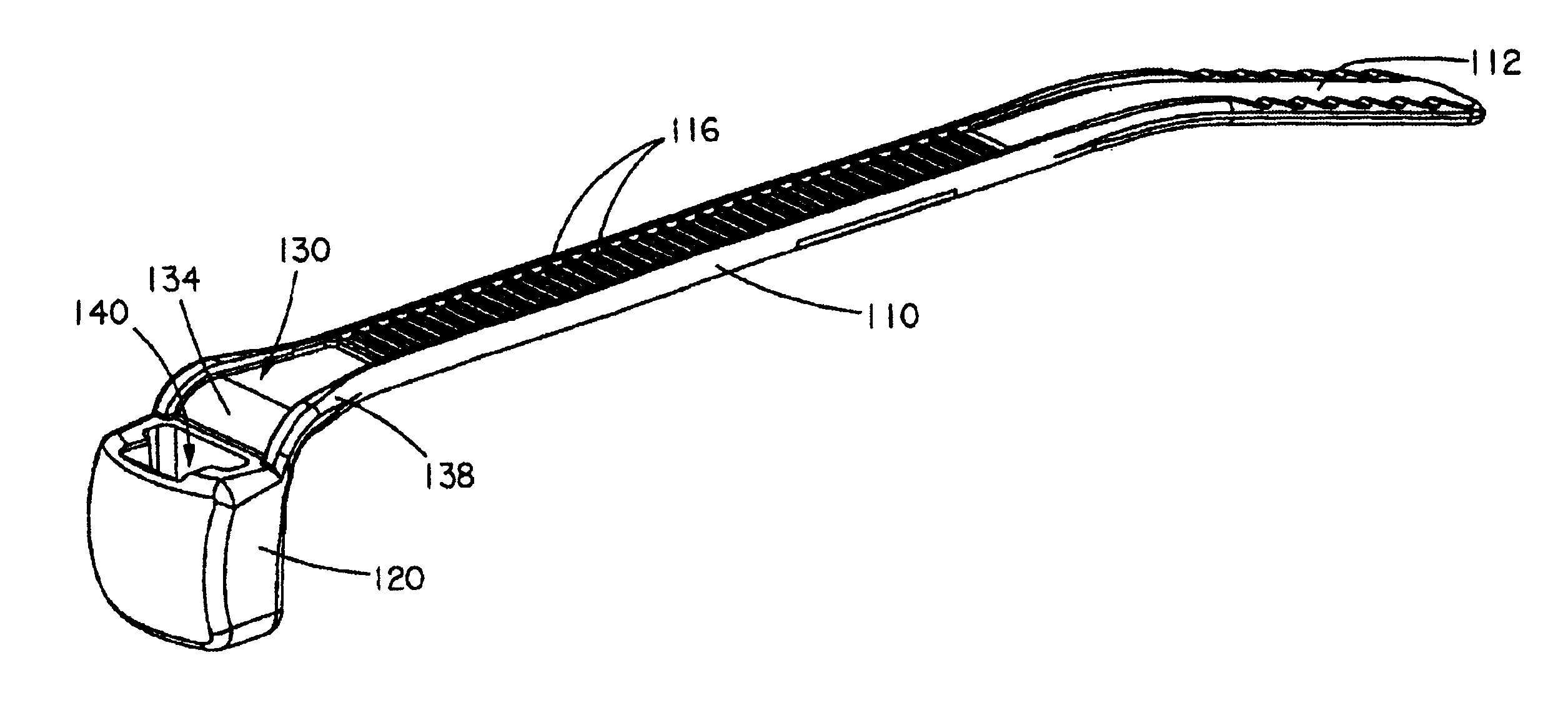
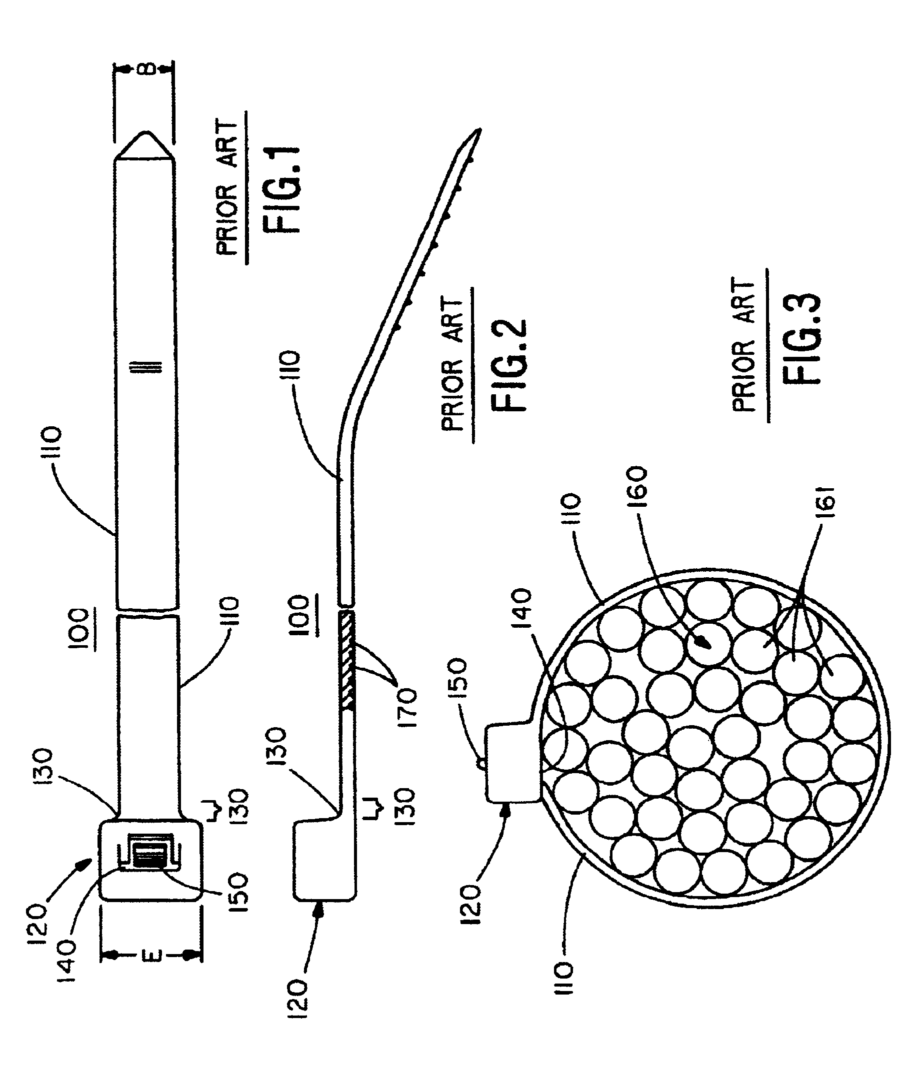
[0042]The invention relates to a cable tie having improved flexibility at a neck section of the cable tie, which is particularly important in a bent neck type cable tie. Conventional cable ties primarily use neck cross-sections that substantially correspond to the cross-section of the strap (see FIG. 10). While this results in a neck section that has a tensile strength equal to the rest of the strap, it results in the previously described problems of bent neck cable ties with a stepped parting line.

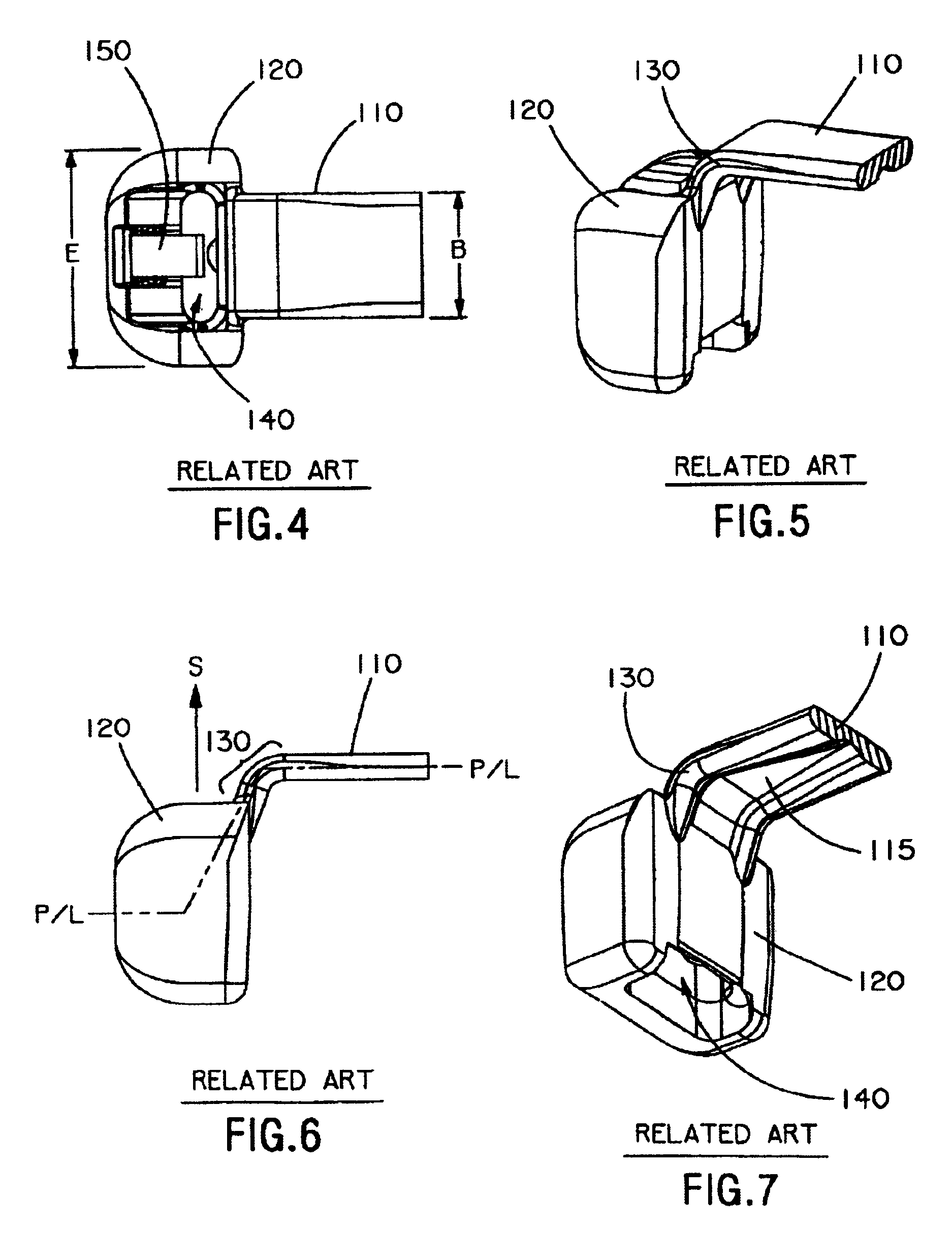
[0043]The strap thickness, parting line angle, and strap body edge radii limit the size of the radii that can transition from cable tie head to neck in a bent neck type cable tie. The general equation for the moment of inertia for a simple rectangular cross-section cable tie is I=(B×T3) / 12 where B is the width of the strap and T is the thickness of the strap. The design of FIGS. 8-9 results in a neck with limited flexibility as the neck cross-section is approximately the same as the cross...


PUM


Abstract

A cable tie is provided that includes an integral cable tie head and strap. The strap includes a first end forming a neck section, a free end opposite the first end, and an intermediate section between the first end and the free end, the intermediate section having a predetermined width B1 and thickness T1 defining a predetermined cross-sectional area. The cable tie head is secured to the neck area of the strap at the first end of the strap, the cable tie head having a width E that is wider than strap width B and including a strap accepting channel containing a locking device. The strap accepting channel is sized to receive the free end of the strap. The neck section has a width that transitions from a width of B to a width E′ that is substantially the same as width E and a thickness T2 that is thinner than T1, the neck section having a cross-sectional area that is at least substantially equal to the cross-sectional area of the intermediate section of the strap so as to have a tensile strength at least equal to a tensile strength of the intermediate section of the strap. The cable tie may be a bent neck type cable tie. Preferably, the neck section has at least one recessed channel defining the reduced thickness T2 and thickened side portions.

Description

BACKGROUND OF THE INVENTION[0001]1. Field of Invention[0002]The present invention relates generally to an advanced neck design for cable ties.[0003]2. Description of Related Art[0004]Cable ties have traditionally been formed by an integral molding of a cable tie head and a cable strap. Most of these cable ties involve a design in which the elongated strap extends straight outward from the cable tie head. An example of such a conventional cable tie design is U.S. Pat. No. 3,949,449 to Caveney et al., which is represented in FIGS. 1-3.[0005]As shown, this conventional cable tie 100 includes an elongated strap 110 extending from an integrally molded cable tie head 120. A neck area 130 is formed at the interface between strap 110 and head 120. Cable tie head 120 includes a strap accepting channel 140 that receives strap 110 and a locking device 150. In use, cable tie 100 can be wrapped around objects such as a bundle of cables 160 and locked in place as known in the art.[0006]With such ...

Claims


Application Information

Patent Timeline
Patent Type & Authority Patents(United States)
IPC IPC(8): B65D63/10B65B13/02B65B27/00B65D63/12F16L3/137H02G3/30
CPCB65D63/1036Y10T24/153Y10T24/1498
Inventor BROWNLEE, JAMES A.KRISEL, ROBERT J.
Owner PANDUIT
Why Eureka
Try Eureka