Magnetic clamping device and method for detecting and controlling an operating state of a magnetic clamping device

A technology of clamping device and magnet device, applied in workpiece clamping devices, electromagnets, manufacturing tools, etc., can solve problems such as insufficient electromagnetic coupling

Inactive Publication Date: 2007-09-19
STAUBLI FAVERGES SA
View PDF6 Cites 3 Cited by
  • Summary
  • Abstract
  • Description
  • Claims
  • Application Information

AI Technical Summary

Problems solved by technology

However, this approach results in insufficient electromagnetic coupling for maintaining the working

Method used


Image

  • Magnetic clamping device and method for detecting and controlling an operating state of a magnetic clamping device
  • Magnetic clamping device and method for detecting and controlling an operating state of a magnetic clamping device
  • Magnetic clamping device and method for detecting and controlling an operating state of a magnetic clamping device

Examples


Embodiment Construction

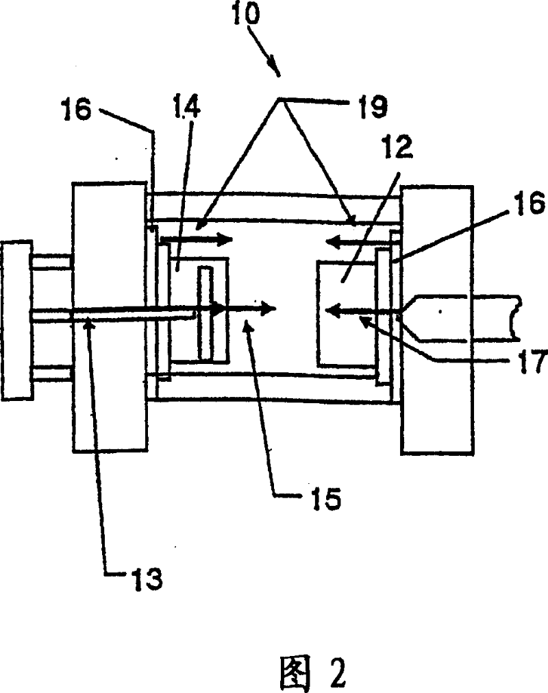
[0042] FIG. 2 schematically shows an embodiment of an injection molding machine 10 having a fixed platen 12 and a movable platen 14 which are clamped by an electromagnetic clamping device (“clamp”) 16 Installed on the injection molding machine 10 respectively, the above-mentioned electromagnetic clamping device 16 is suitable for working as a quick mold changing device. In normal operation, there are many forces against the clamping force generated by the clamp 16, namely, the ejector force 13 due to incorrect machine adjustment, the inertial force 15 during the mold closing stroke, the nozzle pressure 17 and the opening pressure. Mould19.

[0043] In order to counteract these effects and other operating conditions that interrupt the electromagnetic clamping force, an electromagnetic clamping device with a multifunctional sensor system as described below is provided at the clamping interface, ie at the electromagnetic holding unit 110 .

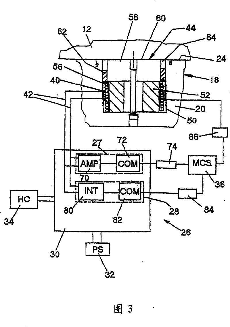
[0044] An embodiment of an electromag...


PUM

PropertyMeasurementUnit
magnetic flux densityaaaaaaaaaa

Abstract

The present invention discloses a magnetic clamping device having at least one magnetic holding unit comprising a switchable magnet generating a magnetic clamping force at a workpiece and a sensing means, wherein said sensing means comprises a search coil adapted to provide a detection signal indicative of a magnetic flux being applicable for at least approximately determining a clamping force exerted on the workpiece to be clamped and a method for detecting an operating state of a magnetic clamping device.

Description

technical field [0001] The invention relates to an electromagnetic clamping device and a method for detecting and controlling the working state of the electromagnetic clamping device. Background technique [0002] In general, clamping devices are necessary in various material handling and production machines such as (industrial) manipulators, manipulators or injection molding machines, e.g. for (releasably) attaching Tools (such as welding torches or suction chucks) or workpieces are attached to the robotic arm of a manipulator or an injection mold is attached to a molding press. [0003] Material handling and production machinery such as manipulators, manipulators or injection molding machines are typically equipped with various sensing devices to ensure that mechanical or hydraulic based coupling mechanisms are properly engaged to keep their work going. In order to minimize downtime (such as for changing manipulator tools) and to maximize the productivity of these kinds o...

Claims


Application Information

Patent Timeline
Patent Type & Authority Patents(China)
IPC IPC(8): B25B11/00H01F7/20B23Q3/15B29C33/32B29C45/17B29C45/64
CPCB29C2045/1746B29C45/1742B25B11/002H01F2007/208H01F13/00H01F7/206
Inventor M·A·约翰逊S·C·巴顿
Owner STAUBLI FAVERGES SA
Why Eureka
Try Eureka