Movable type push and pull clamping device

A clamping device, mobile technology, applied in the field of mobile push-pull clamping device, can solve the problems of poor clamping effect, inconvenient loading and unloading, complicated structure, etc., and achieve the effect of convenient loading and unloading, good clamping effect and simple structure

Inactive Publication Date: 2018-02-23
成都中源红科技有限公司
View PDF0 Cites 4 Cited by
  • Summary
  • Abstract
  • Description
  • Claims
  • Application Information

AI Technical Summary

Problems solved by technology

[0002] In mechanical processing, it is usually necessary to use a clamping device to clamp the workpiece first, and then process on the workpiece, so the clamping device is widely used. The traditional clamping device has complex structure, inconvenient loading and unloading, and poor clamping effect. Problems that affect the quality of workpiece processing

Method used


Image

  • Movable type push and pull clamping device

Examples


Embodiment Construction

[0010] The present invention will be further described below in conjunction with the accompanying drawings.

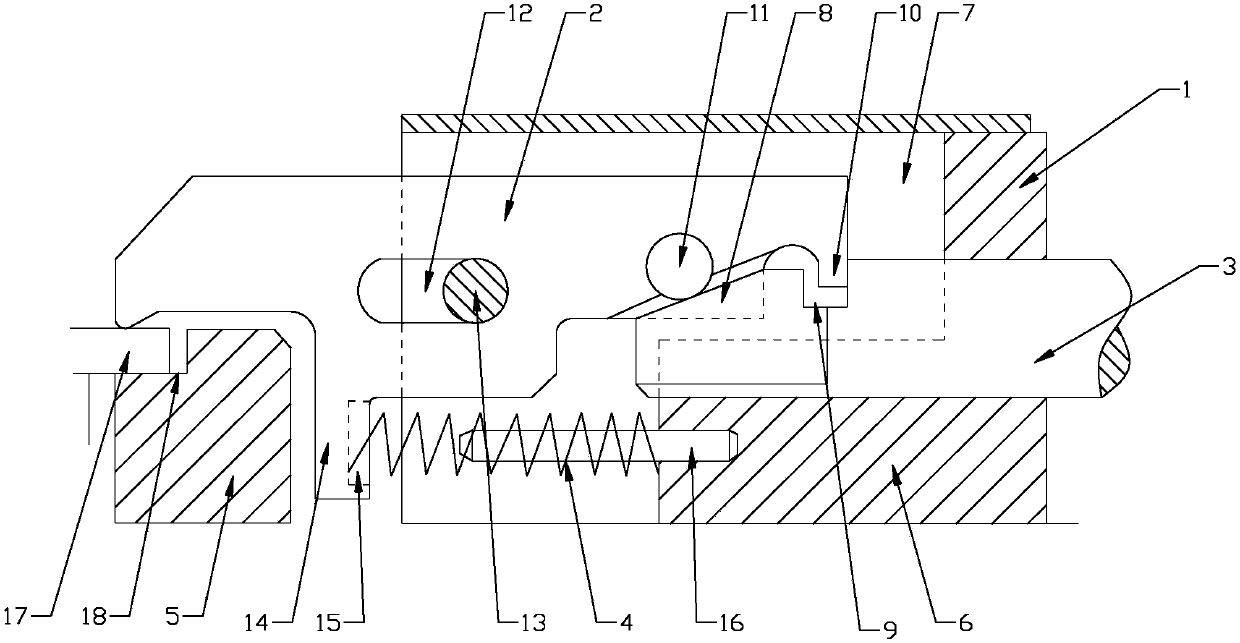
[0011] Such as figure 1 As shown, the present invention provides a mobile push-pull clamping device, including a base 1, a pressure plate 2, a push rod 3 and a compression spring 4, wherein the base 1 includes a support platform 5 and a mounting platform 6, and the installation Table 6 is provided with installation cavity 7, and the top of described installation cavity 7 is provided with dust-proof cover plate 8, and described support platform 5 is provided with the limit platform 18 that has preliminary limit effect to workpiece 17, and described push rod 3 levels Extending into the installation cavity 7 and slidingly connected with the installation platform 6, the push rod 3 is provided with a wedge block 8 at the end of the installation cavity 7, and the top of the push rod 3 is close to the wedge block 8 The position of the groove 9 is provided, and the right end ...


PUM


Abstract

The invention relates to a clamping device, in particular to a mobile push-pull clamping device, comprising a base, a pressure plate, a push rod and a compression spring, the base includes a support table and an installation table, the installation table is provided with an installation cavity, and the push rod It extends horizontally into the installation cavity and is slidably connected to the installation table. The end of the push rod is located in the installation cavity with a wedge block, the upper part of the push rod close to the wedge block is provided with a groove, and the right end of the pressure plate is provided with a collision block and a roller , the striker extends into the groove, the roller slides with the wedge-shaped surface of the wedge-shaped block, the middle of the pressure plate is horizontally provided with a strip-shaped groove, and the strip-shaped groove slides with the pin set on the installation table. The pressure plate also includes a downward extending Mounting block for mounting compression springs. The mobile push-pull clamping device adopting the technical scheme of the present invention has the characteristics of simple structure, convenient assembly and disassembly, and good clamping effect.

Description

technical field [0001] The invention relates to a clamping device, in particular to a movable push-pull clamping device. Background technique [0002] In mechanical processing, it is usually necessary to use a clamping device to clamp the workpiece first, and then process on the workpiece, so the clamping device is widely used. The traditional clamping device has complex structure, inconvenient loading and unloading, and poor clamping effect. Problems that affect the quality of workpiece processing. Contents of the invention [0003] The purpose of the present invention is to solve the above-mentioned technical problems and provide a mobile push-pull clamping device, which has the characteristics of simple structure, convenient assembly and disassembly, and good clamping effect. [0004] In order to solve the above technical problems, the present invention adopts a mobile push-pull clamping device, which includes a base, a pressure plate, a push rod and a compression spri...

Claims


Application Information

Patent Timeline
Patent Type & Authority Applications(China)
IPC IPC(8): B23Q3/06
CPCB23Q3/06
Inventor 黄光辉
Owner 成都中源红科技有限公司
Why Eureka
Try Eureka