Clamping device

A clamping device and clamping body technology, applied in the field of mechanical processing, can solve the problems of affecting the clamping precision, low clamping precision, inconvenient workpiece processing, etc., and achieve the effect of reliable clamping and guaranteed precision

Inactive Publication Date: 2017-09-19
四川利丰航空科技有限公司
View PDF0 Cites 4 Cited by
  • Summary
  • Abstract
  • Description
  • Claims
  • Application Information

AI Technical Summary

Problems solved by technology

[0002] When the workpiece is clamped and positioned, it is often clamped by pressing plates, bolts, etc. The clamping accuracy of this clamping method is not high, and it takes a long time to twist back and forth when replacing the workpiece, which is

Method used


Image

  • Clamping device
  • Clamping device

Examples


Embodiment Construction

[0016] The present invention will be further described below in conjunction with accompanying drawing, protection scope of the present invention is not limited to the following:

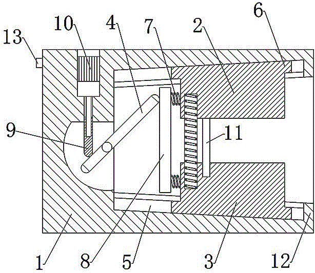
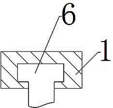
[0017] Such as figure 1 As shown, a clamping device includes a base body 1, an upper clamping body 2, a lower clamping body 3 and a rotating shaft 4. A cavity A and a cavity B are opened in the base body 1, and the outer end of the cavity A is large and The inner end is small and the outer end of the cavity A is close to the end of the base 1. The inner wall of the cavity A has a tenon-shaped groove 5, and the upper clamping body 2 and the lower clamping body 3 are provided with a tenon-shaped head 6. The upper clamping body 2 and the lower clamping body 3 are placed in the cavity A and the tenon-shaped head 6 on it is adapted to the tenon-shaped groove 5. The cavity B is located at the inner end of the cavity A and is connected. The rotating shaft 4 It is hinged on the inner wall of chamber B along...


PUM


Abstract

The invention discloses a clamping device, which includes a base body, an upper clamping body, a lower clamping body and a rotating shaft. A cavity A and a cavity B are opened in the base body. The outer end of the cavity A is large and the inner end is small, and the cavity A At the outer end and the end close to the base body, the inner wall of cavity A is provided with tenon-shaped grooves, and the upper and lower clamping bodies are equipped with tenon-shaped heads, and the upper and lower clamping bodies are placed in the cavity. The tenon-shaped head in and on A is adapted to the tenon-shaped groove. The chamber B is located at the inner end of the chamber A and is connected. The rotating shaft is hinged on the inner wall of the chamber B along the vertical plane. One end of the rotating shaft is located at The other end is in cavity B and the other end is located in cavity A. A pressure plate is connected to the inner surface of the upper clamping body and the lower clamping body through spring A, and the pressure plate is in contact with the end of the rotating shaft; The contacting ejector rod is connected with the output shaft of the motor through threads, and the motor is fixed on the base body. The beneficial effects of the invention are: convenient clamping, fastening and reliable clamping.

Description

technical field [0001] The invention relates to the technical field of machining, in particular to a clamping device. Background technique [0002] When the workpiece is clamped and positioned, it is often clamped by pressing plates, bolts, etc. The clamping accuracy of this clamping method is not high, and it takes a long time to twist back and forth when replacing the workpiece, which is not convenient for the processing of the workpiece . Although some clamping devices have been improved, usually the clamping force is small, and there will be relative displacement between different clamping blocks, which affects the clamping accuracy. The present invention proposes a clamping device structure, which solves the above problems more practically, perfectly and conveniently. Contents of the invention [0003] The object of the present invention is to overcome the disadvantages of the prior art, and provide a clamping device that is convenient for clamping, fastening and ...

Claims


Application Information

Patent Timeline
IPC IPC(8): B23Q3/06
CPCB23Q3/067
Inventor 韦银
Owner 四川利丰航空科技有限公司
Why Eureka
Try Eureka