Auxiliary mechanism for electric steel tube rod transportation

A technology of electric steel pipes and auxiliary mechanisms, applied in the direction of internal accessories, etc., can solve the problems of electric steel pipe poles colliding with each other, falling, damage, etc., and achieve the effects of increasing frictional resistance, increasing firmness, and ensuring stability

Active Publication Date: 2020-02-25
张新兴
View PDF7 Cites 4 Cited by
  • Summary
  • Abstract
  • Description
  • Claims
  • Application Information

AI Technical Summary

Problems solved by technology

The traditional iron tower covers a large area, and its shape is not in harmony with the modern urban environment. The use of high-voltage cables is expensive; the use of reinforced concrete poles has not been able to solve the problems of longitudinal and circumferential cracks. Electric steel pipe poles The structure is simple, the force is clear, the processing and manufacturing are easy, and the maintenance workload is small, so it is widely used in the power supply network of modern cities
[0003] The use of electric steel pipe poles is increasing, and the places where they are used are also different. Therefore, it is necessary to transport the electric steel pipe poles to designated places for use, while the existing electric steel pipe poles are usually transported by trucks. Electric steel pipe poles After the rod is placed in the truck body, it is fixed by iron chains, ropes and other tools. Open, so that the electric steel pipe poles collide with each other or hit the car body, causing damage or even falling, affecting the subsequent transportation efficiency

Method used


Image

  • Auxiliary mechanism for electric steel tube rod transportation
  • Auxiliary mechanism for electric steel tube rod transportation
  • Auxiliary mechanism for electric steel tube rod transportation

Examples


Embodiment Construction

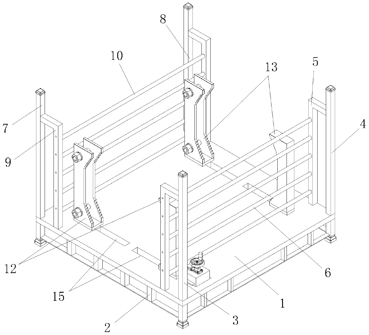
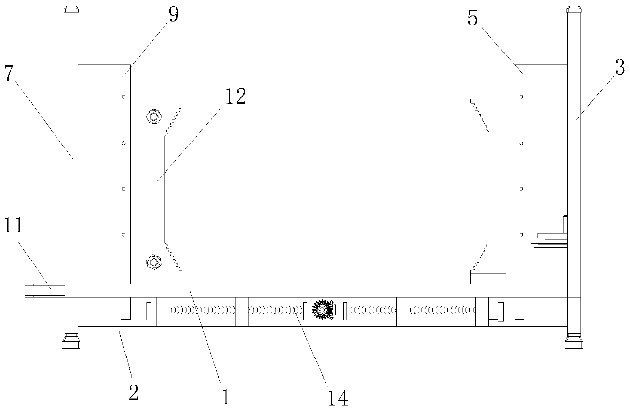
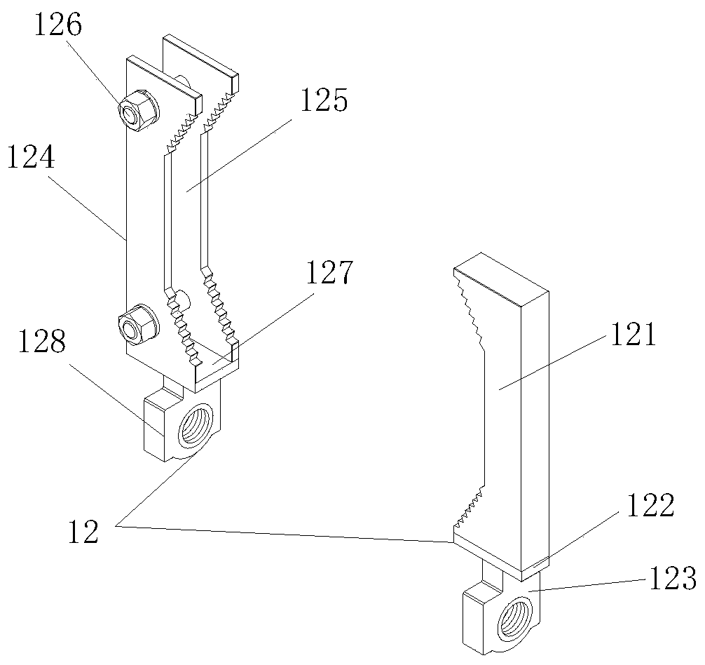
[0033] The following will be combined with Figure 1-9 The present invention is described in detail, and the technical solutions in the embodiments of the present invention are clearly and completely described. Apparently, the described embodiments are only some of the embodiments of the present invention, not all of them. Based on the embodiments of the present invention, all other embodiments obtained by persons of ordinary skill in the art without making creative efforts belong to the protection scope of the present invention.

[0034]The present invention provides an auxiliary mechanism for the transportation of electric steel pipe poles through improvement, including a bottom plate 1, a supporting chassis 2, a first side frame 3, a second side frame 4, a first inner frame 5, and a first horizontal rail 6. The third side frame 7, the fourth side frame 8, the second inner frame 9, the second rail 10, the outer plate 11, the first clamping structure 12, the second clamping s...


PUM


Abstract

The invention discloses an auxiliary mechanism for electric steel tube rod transportation. The auxiliary mechanism comprises a bottom plate, a supporting bottom frame, a first side frame, a second side frame, a first inner frame, a first transverse cross bar, a third side frame, a fourth side frame, a second inner frame, a second cross bar, an outer connecting plate, a first clamping structure, asecond clamping structure, a clamping transmission device and a slide slot. According to the auxiliary mechanism disclosed by the invention, the first clamping structure and the second clamping structure are separately mounted at front and rear sides of the upper end of the bottom plate, the clamping transmission device arranged on the bottom of the bottom plate can transit for synchronously moving the first clamping structure and the second clamping structure, so that two positions of an electric steel tube rod are synchronously clamped, and clamping force and stability is guaranteed; and theelectric steel tube rod is clamped more firmly, so that stability can be guaranteed while the electric steel tube rod is transported, and transportation of the electric steel tube rod is convenient.

Description

technical field [0001] The invention relates to the field related to the transportation of electric steel pipe poles, in particular to an auxiliary mechanism for electric steel pipe pole transportation. Background technique [0002] In recent years, due to the rapid development of urban construction and the rapid increase of electricity load, the power supply network can no longer meet the needs of the development of electricity load. The traditional iron tower occupies a large area, and its shape is not in harmony with the modern urban environment. It is expensive to use high-voltage cables; it uses reinforced concrete poles, and its longitudinal and circumferential cracks have not been well resolved. Electric steel pipe poles The structure is simple, the force is clear, the processing and manufacturing are easy, and the maintenance workload is small, so it is widely used in the power supply network of modern cities. [0003] The use of electric steel pipe poles is increas...

Claims


Application Information

Patent Timeline
Patent Type & Authority Applications(China)
IPC IPC(8): B65D25/10B65D25/02
CPCB65D25/02B65D25/10
Inventor 游永鹏
Owner 张新兴
Why Eureka
Try Eureka