
Mounting equipment of electronic parts

An electronic component installation and electronic component technology, applied in the direction of electrical components, electrical components, semiconductor/solid-state device testing/measurement, etc., can solve the problems such as the inability to find the inherent offset of the loading position and the inability to identify clear images, and achieve accurate And stable parts recognition, improved lighting effect, compact installation device effect

Inactive Publication Date: 2008-04-23
JUKI CORP
View PDF9 Cites 0 Cited by
  • Summary
  • Abstract
  • Description
  • Claims
  • Application Information

AI Technical Summary

Problems solved by technology

[0007] However, even with this method, a clear image cannot be recognized, and the inherent displacement of the electronic component mounting position of the electronic component mounting device that is sufficiently satisfactory cannot be obtained.

Method used


Image

  • Mounting equipment of electronic parts
  • Mounting equipment of electronic parts
  • Mounting equipment of electronic parts

Examples


Embodiment Construction

[0025] Next, embodiments of the electronic component mounting apparatus of the present invention will be described.

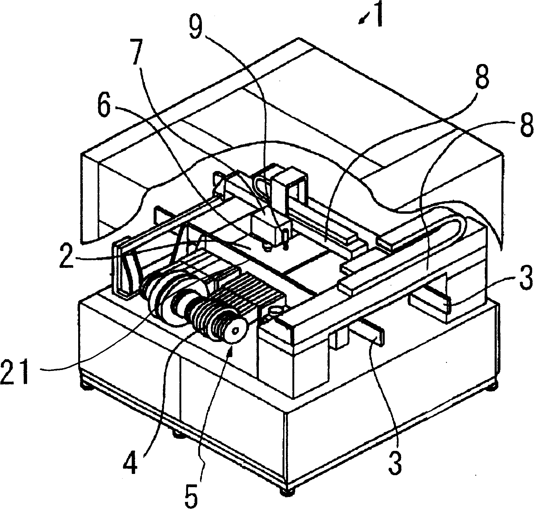
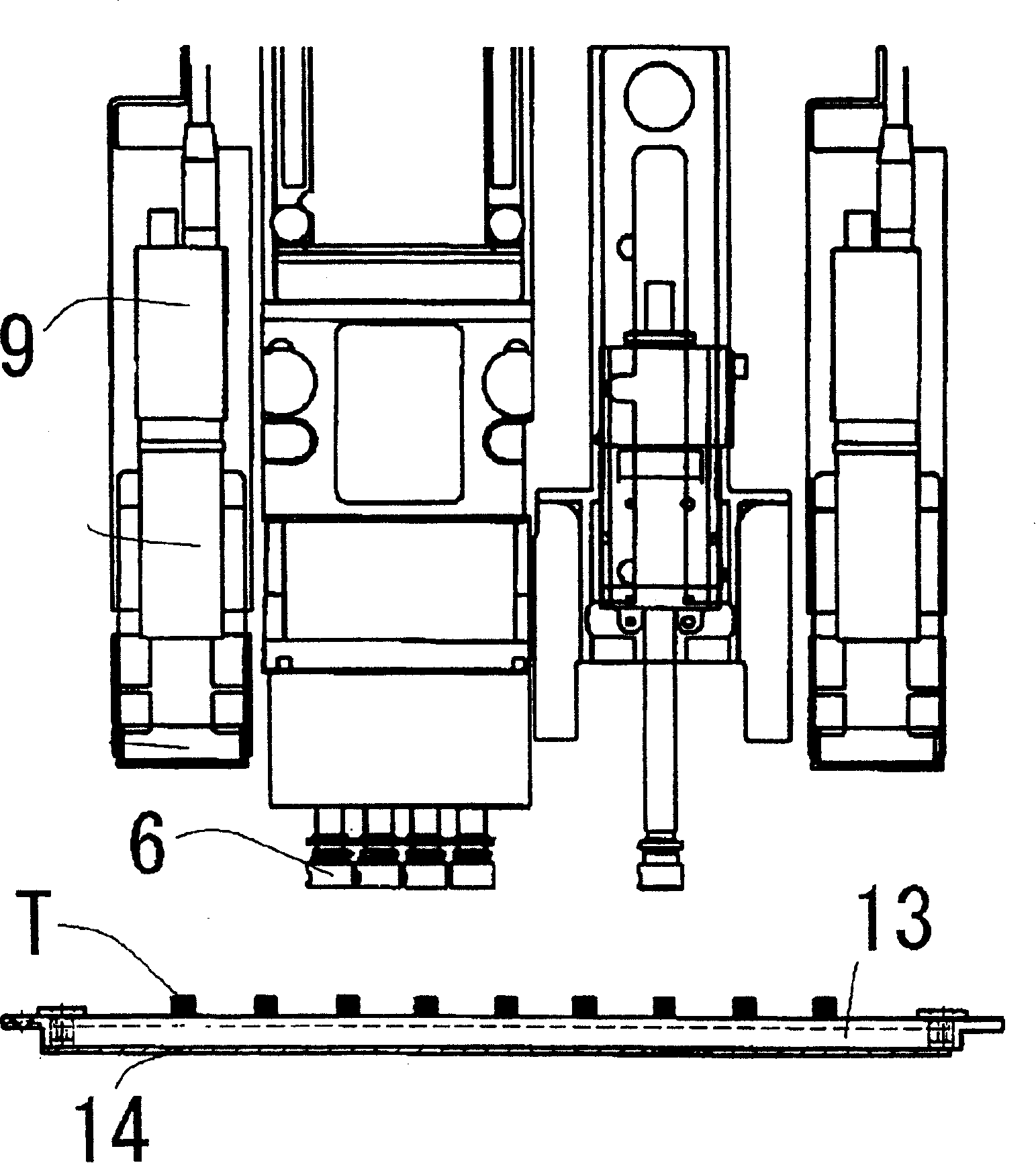
[0026] exist figure 1 , figure 2 , Figure 7 Among them, the electronic component mounting apparatus 1 is roughly composed of the following parts: a substrate conveying part 3 that can place a substrate 2 on a component mounting part 21; a component supply part 5 composed of a plurality of tape feeders 4, the plurality of tape a feeder for supplying electronic components mounted on a substrate 2 placed on the component loading section 21; a component loading head 7 having an adsorption nozzle 6 for absorbing electronic components and loading them onto a component loading position on the substrate 2; XY moving mechanism 8 (comprising X-axis motor 24, Y-axis motor 25) that component loading head 7 moves in the horizontal direction; photographing the fiducial marks on the substrate and the identification camera (imaging device) 9 of electronic components after...


PUM


Abstract

The purpose of this invention is to provide an electronic part packaging device which stably recognizes a position for mounting an electronic part, and measures a peculiar deviation of the position for mounting the electronic part peculiar to the electronic part packaging device. The electronic part packaging device comprises a part inspection mounting part composed of a transparent member provided in the shift range of a part mounting head, an imaging device provided in the part mounting head for imaging the electronic part, and a luminaire which is disposed on a side opposed to a recognizer across the part inspection mounting part to form the shadow of the electronic part.

Description

technical field [0001] The present invention relates to an electronic component mounting apparatus having a device for measuring the mounting accuracy of a mounting position of an electronic component on a substrate. Background technique [0002] Patent Document 1 JP-A-2003-142891 [0003] Conventionally, as such an electronic component mounting device, a device is known that uses a test board and a test electronic component to measure the amount of positional displacement inherent to the electronic component mounting device before the actual device is operated in order to improve the mounting accuracy of the electronic component. , based on the measured value, the mounting position is corrected using the inherent positional displacement of the electronic component mounting device with respect to the substrate. [0004] However, according to this electronic component mounting apparatus, the electronic component for testing mounted on the substrate for testing is reflected a...

Claims


Application Information

Patent Timeline
Patent Type & Authority Patents(China)
IPC IPC(8): H01L21/66H05K13/04H05K13/08
Inventor 东盛夫
Owner JUKI CORP
Learn More