CD machine

A technology for optical disc drives and optical discs, which is applied to instruments, structural components of record carriers, data recording, etc., and can solve the problems of clamping discs, disc drives unable to operate, discs easily detached from trays, etc.

Inactive Publication Date: 2008-05-21
LITE ON IT
View PDF6 Cites 0 Cited by
  • Summary
  • Abstract
  • Description
  • Claims
  • Application Information

AI Technical Summary

Problems solved by technology

When the above-mentioned upright tray type optical disc drive is in use, since the tray carrying the optical discs is also in an upright state, it cannot provide a large area to carry the discs, so that the optical discs are easily separated from the tray during the loading process of the tray, so that the tray cannot be loaded. The disc is clamped smoothly, which causes the disc drive to fail to operate

Method used


Image

  • CD machine
  • CD machine
  • CD machine

Examples


Embodiment Construction

[0051] According to the above purpose, a preferred embodiment is hereby given together with drawings to illustrate the technical means used in the present invention and its effects.

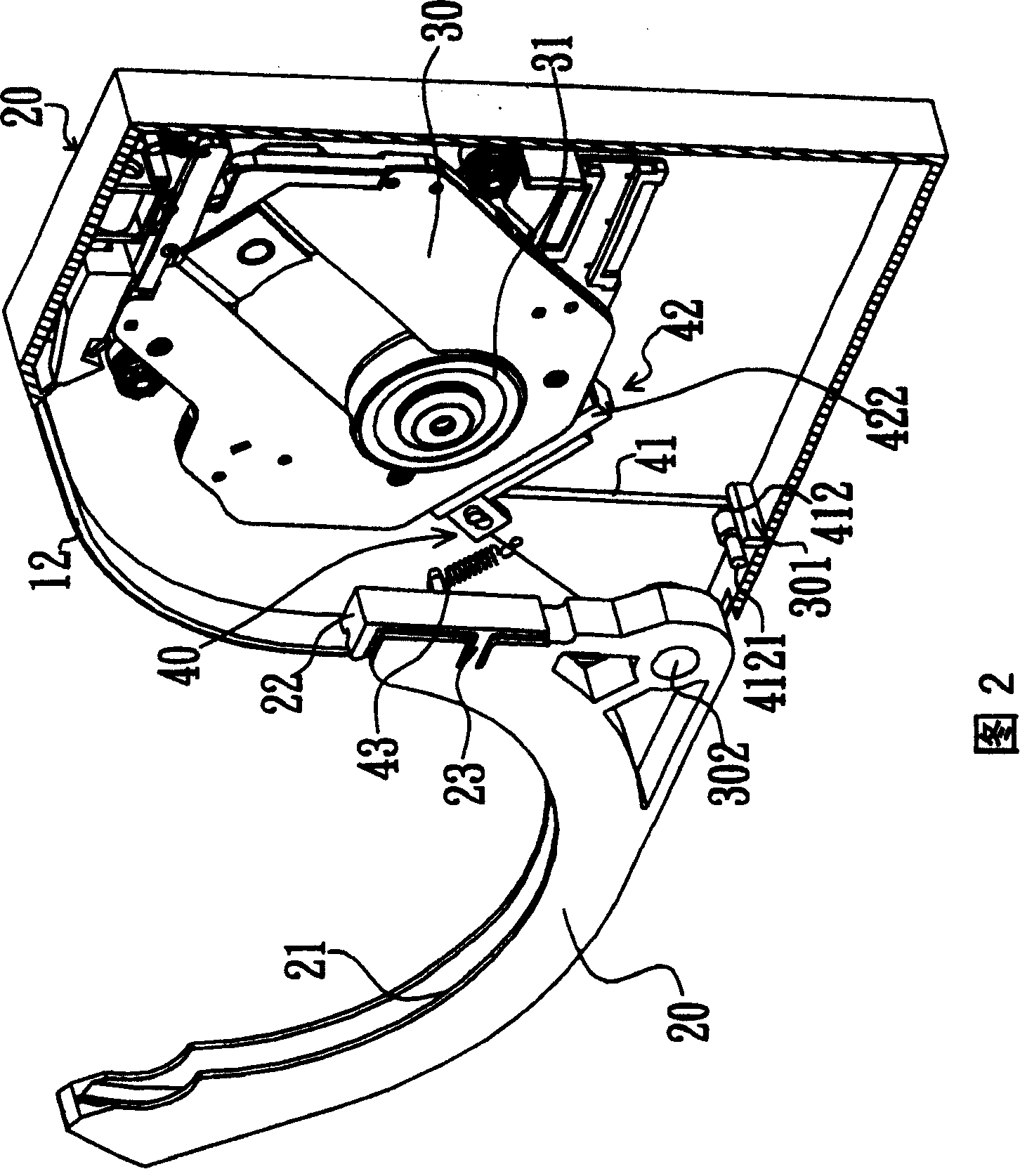
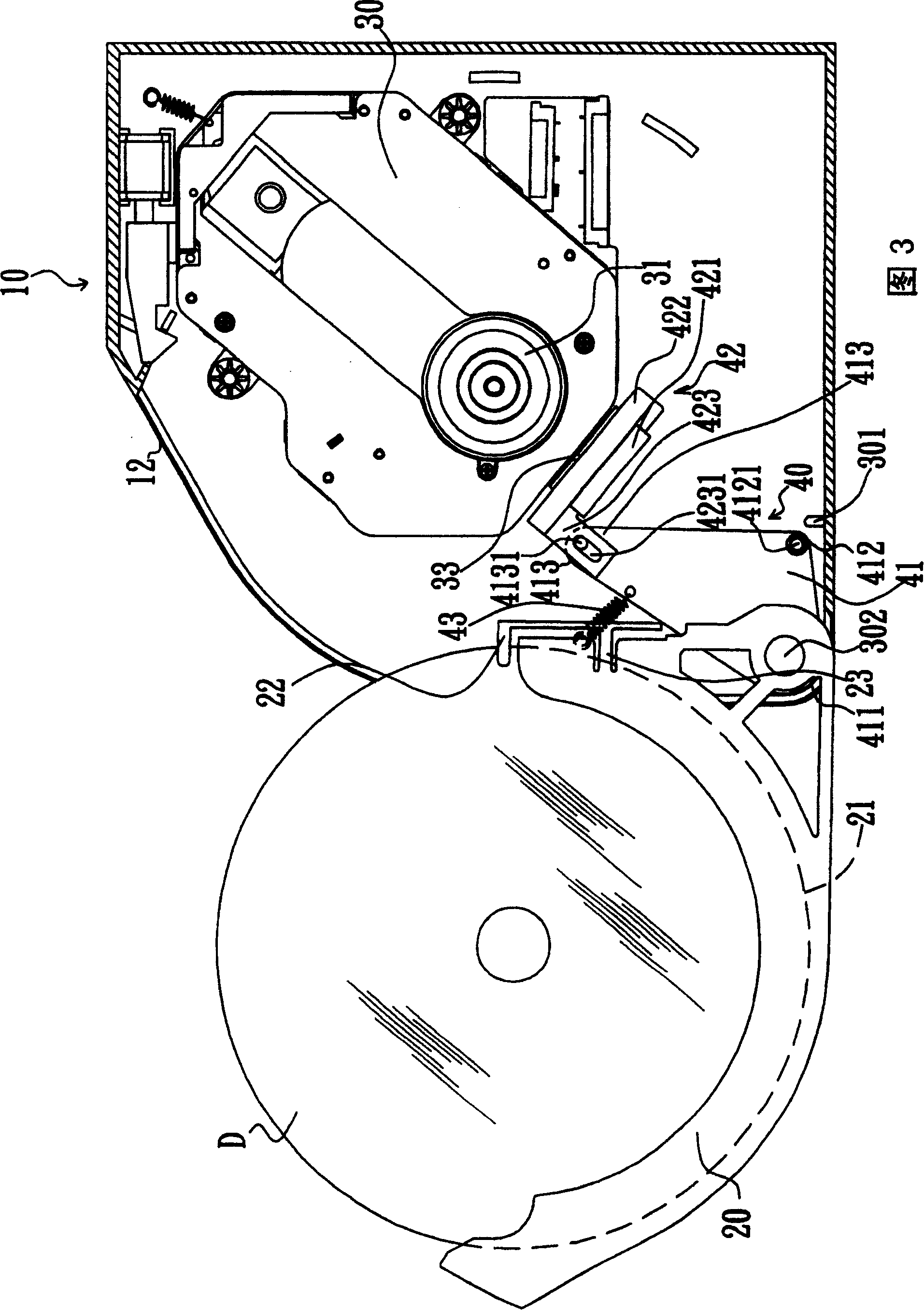
[0052] Please refer to Fig. 2, Fig. 3 and Fig. 4, Fig. 2 is a combined perspective view of the optical disc drive of the present invention, Fig. 3 is a cross-sectional view of the disc carrying device of the present invention, and Fig. 4 is a disc carrier of the present invention Cutaway view of the device loading enclosure.

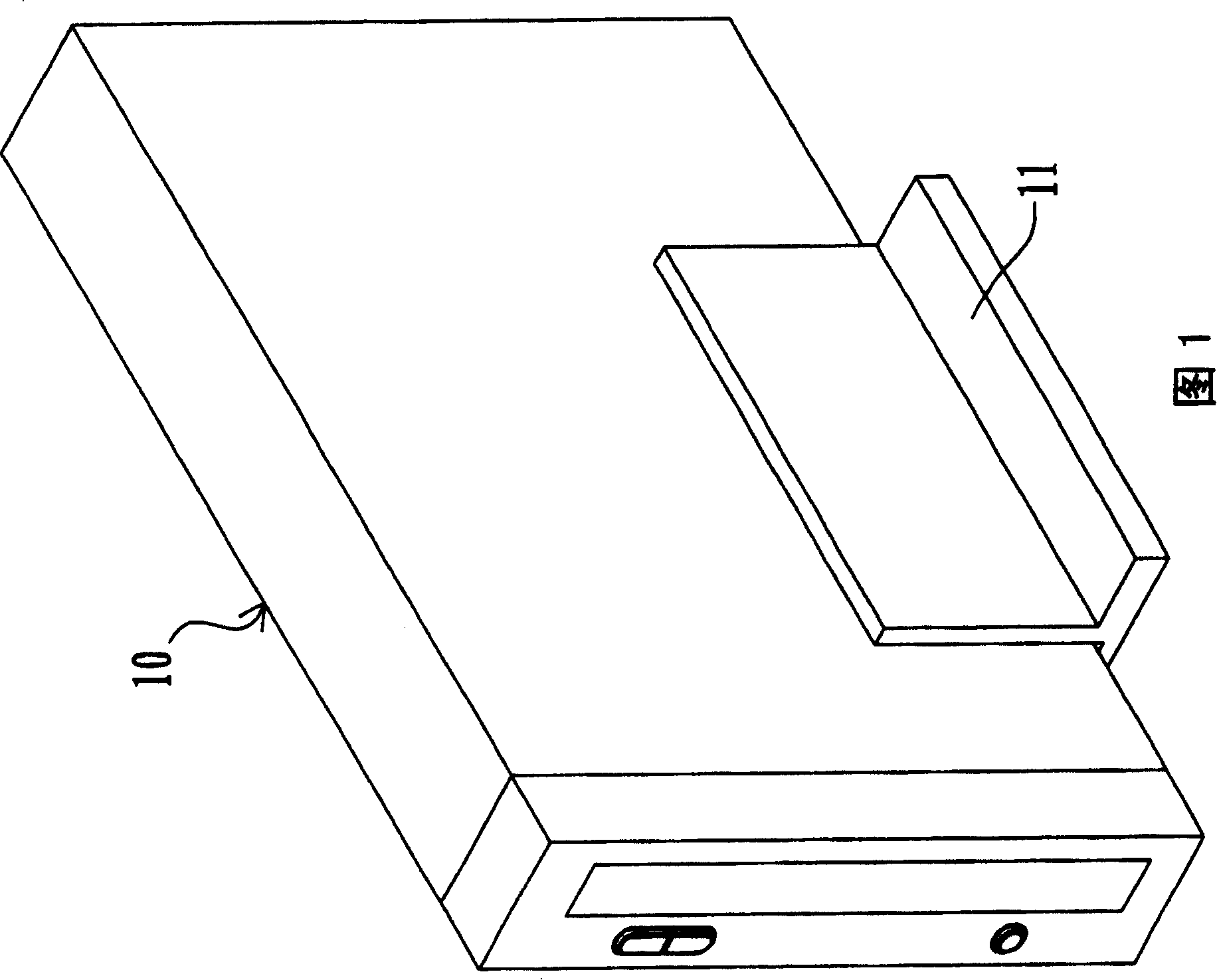
[0053] As shown in the figure, the optical disc player 10 of the present invention includes a housing 11, a disc carrier 20 for carrying the optical disc D, a base 30 and a linkage mechanism 40; one side of the housing 11 has a through slot 12, wherein the optical disc carrying device 20 is pivotally connected to one side of the through groove 12, so that the optical disc carrying device 20 can be carried out and loaded into the casing 11 in a rotating manner, and the optic...


PUM


Abstract

The related CD machine comprises: a shell with a side slot, a CD support device rotated through the slot to load the machine, a base with a shaft and reading module, and a drive mechanism between base and support device to drive the base from a first position to the second to read CD data.

Description

technical field [0001] The invention relates to an optical disc drive, in particular to an optical disc drive for loading and unloading optical discs in a rotating manner. Background technique [0002] With the maturity and popularization of optical disc drive technology, in order to diversify products and meet different needs, various ways of loading and unloading optical discs have been developed, such as: tray type, clamshell type, cassette type and slot-in type optical disc drive wait. The most common one is the tray-type optical disc drive, which mainly uses a tray that can carry optical discs to load the body, and then drives the base inside the body to make it rise at an angle, so that The spindle motor drives the optical disc to rotate for the optical disc drive to read data on the optical disc. [0003] Generally, tray-type CD-ROMs can be divided into vertical and horizontal CD-ROMs. Please refer to FIG. 1 . FIG. 1 is a schematic diagram of the appearance of a co...

Claims


Application Information

Patent Timeline
Patent Type & Authority Patents(China)
IPC IPC(8): G11B17/04G11B33/00
Inventor 吴俊廷李成富
Owner LITE ON IT
Why Eureka
Try Eureka