Pulley guide loading device

A technology of loading device and pulley, which is used in the testing of measuring devices, instruments, and mechanical parts, etc., can solve the problem that the test piece cannot be loaded, and achieve the effect of simple design.

Inactive Publication Date: 2013-04-17
CHINA AIRPLANT STRENGTH RES INST
View PDF8 Cites 8 Cited by
  • Summary
  • Abstract
  • Description
  • Claims
  • Application Information

AI Technical Summary

Problems solved by technology

[0004] The object of the present invention is to provide a pulley-guided loading device for the actuator, which converts the line of force action from the vertical direction to the horizontal direction, and converts the vertical loading of the actuator into the horizontal loading on the ground, which solves the problem that the test piece is close to the ground. point can not load the problem

Method used


Image

  • Pulley guide loading device

Examples


Embodiment Construction

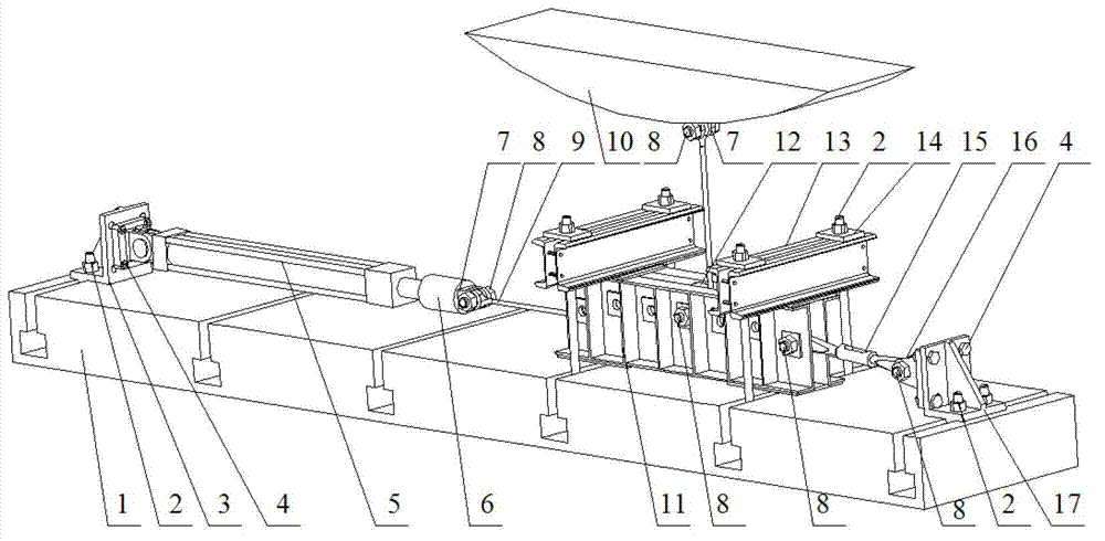
[0017] see figure 1 , the pulley guide loading device of the present invention comprises a plant floor rail 1, anchor bolts 2, a first actuator mounting seat 3, a fixing bolt 4, an actuator 5, a sensor 6, connecting ears 7, connecting bolts 8, and a steel wire rope 9 , Test piece 10, guide pulley seat 11, pulley 12, pressure beam 13, gasket 14, turnbuckle 15, fixed ears 16, second actuator mounting seat 17. Wherein, the pulley 12 is installed in the guide pulley seat 11 by connecting bolts 8, the actuator 5 is installed on the first actuator mount 3 by fixing bolts 4, one end of the steel wire rope 9 is connected to the test piece 10, and the other end is passed through the pulley. 12 After the guide, extend the guide pulley seat 11 wire rope channel to pass through, and connect to the actuator 5 through the connecting bolt 8, the connecting ears 7, and the sensor 6 successively; One end that does not pass through, the other end is also fixed on the fixed double ear 16 by con...


PUM


Abstract

The invention relates to a pulley guide loading device, in particular to a pulley guide loading device for testing an airplane structure. The pulley guide loading device comprises anchor bolts, a first actuating cylinder mounting seat, fixing bolts, an actuating cylinder, a sensor, double connecting lugs, connecting bolts, a steel wire rope, a guide pulley seat, a pulley, pressing beams, gaskets, a turn buckle, double fixing lugs and a second actuating cylinder mounting seat. According to the pulley guide loading device, the perpendicular loading of a near-surface downward loading point of a test piece is converted into horizontal ground loading, so that the problem that the actuating cylinder cannot be perpendicularly arranged or a reserved stroke of a piston rod of the actuating cylinder is insufficient after the actuating cylinder is perpendicularly arranged, and a perpendicular test load cannot be applied due to the fact that the near-surface download loading point of the test piece is close to the ground in a test in the airplane structure is solved.

Description

technical field [0001] The invention relates to a pulley guide loading device, in particular to a pulley guide loading device used for aircraft structure tests. Background technique [0002] In the aircraft structure test, the selection of the support height of the test piece is an important issue in the test planning. Considering the load characteristics and safety of the test items, the support height of the test piece is sometimes reduced. However, reducing the test support height will make it more difficult to implement downward loading of the test piece near the ground. The reason is that the position of the downward loading point near the ground of the test piece is close to the ground, so that the actuator cannot be installed vertically or the piston rod of the actuator after the vertical installation has insufficient reserved travel, and the test load cannot be applied. [0003] In the past, the actuator at the downward loading point of the test piece was installed...

Claims


Application Information

Patent Timeline
Patent Type & Authority Applications(China)
IPC IPC(8): G01M13/00
Inventor 杜星王征余寅强李小宁米征刘卓桢
Owner CHINA AIRPLANT STRENGTH RES INST
Why Eureka
Try Eureka