Supercharge Your Innovation With Domain-Expert AI Agents!

Stepped plunger for use with an ultrasonic sensor

A technology of fluid distribution and plunger, which is applied in the use of sound waves/ultrasonic waves/infrasonic waves to analyze solids, analyze materials, and use sound waves/ultrasonic waves/infrasonic waves for material analysis. It can solve problems such as increased materials and costs, wrong readings, and increased cycles.

Inactive Publication Date: 2008-06-25
SONOCO DEV INC
View PDF5 Cites 0 Cited by
  • Summary
  • Abstract
  • Description
  • Claims
  • Application Information

AI Technical Summary

Problems solved by technology

When this type of plunger uses an ultrasonic sensor, the concave upper surface cancels out the ultrasonic signal, resulting in false readings
To alleviate this problem, the male plunger can be molded with a flat backside so that the reflected ultrasonic signal is good, but this solution requires increased material and expense
Also, the flat rear side is molded on the male plunger, resulting in an unacceptably long cycle (production) period due to the increased time required to cool the extra thermoplastic material contained in the latest molded plunger

Method used


Image

  • Stepped plunger for use with an ultrasonic sensor
  • Stepped plunger for use with an ultrasonic sensor
  • Stepped plunger for use with an ultrasonic sensor

Examples


Embodiment Construction

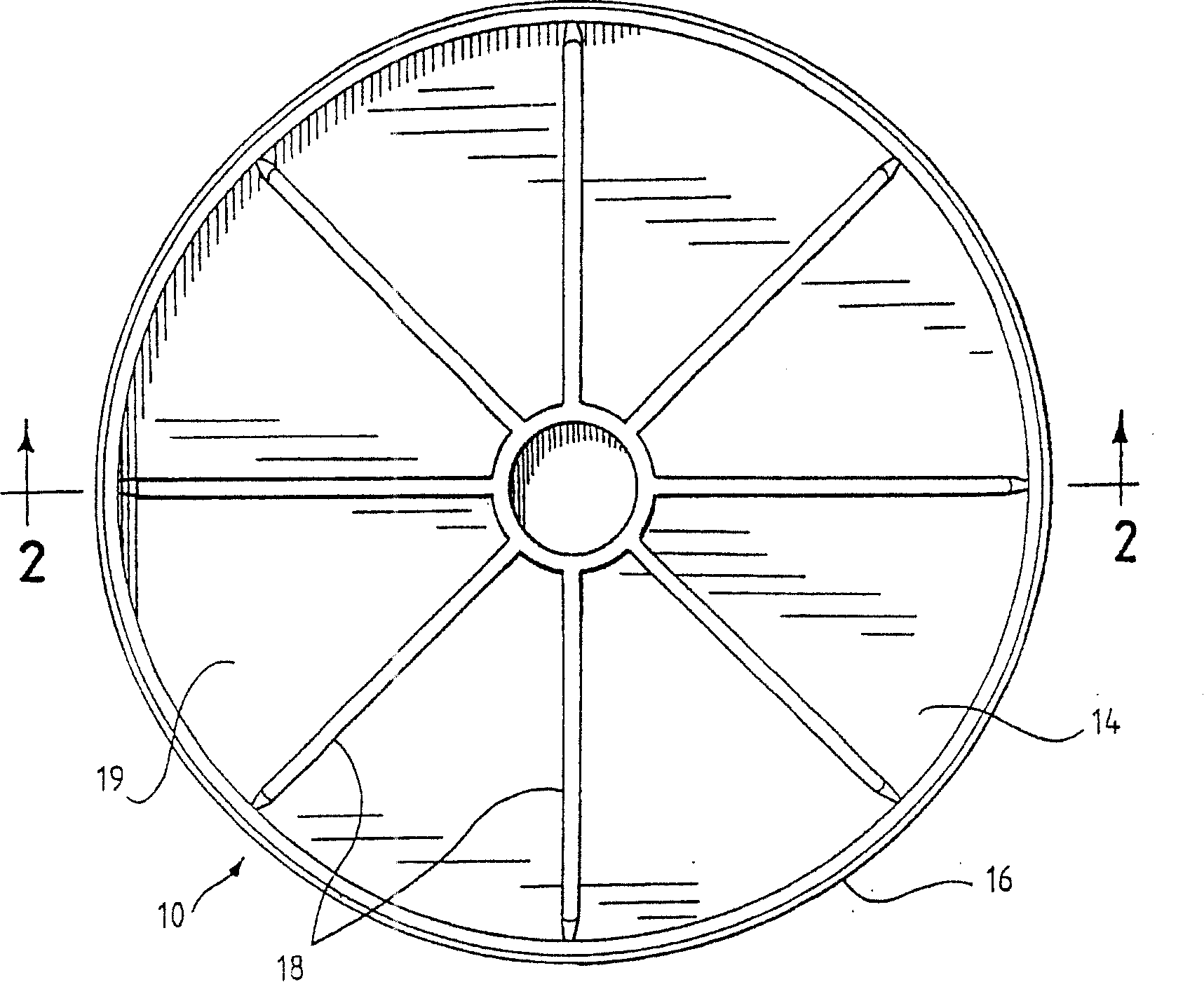
[0022] Turn around and look at the picture, figure 1 and 2 A conventional lithographic ink cartridge plunger 10 having a flat bottom (ink facing) surface 12 is shown. The plunger 10 is generally cup-shaped and includes a bottom wall 14 and a side wall 16 extending upwardly from the periphery of the bottom wall 14 . When the plunger 10 travels through the cartridge, such as the one shown in Figure 7, the flat bottom surface 12 pushes the ink, causing it to be expelled through the nozzle. Reinforcing ribs 18 have been molded into the rear side 19 of the bottom wall 14 to minimize twisting and deformation of the plunger 10 when subjected to high pressures.

[0023] maybe best as figure 2 As shown, the vertical height of the ribs 18 varies along their length, which can lead to inaccurate readings of the plunger position with the ultrasonic signal. A disc (not shown) with a flat reflective surface could be placed below the plunger 10 and above the ribs 18, but this would requi...


PUM


Abstract

An improved plunger (40) for fluid dispensing cartridges used in automated dispensing systems. The plunger (40) helps control the reflection of ultrasonic signals used to sense the position of the plunger (40) as it moves within the cartridge tube (60). The plunger (40) has a convex bottom, ink-facing surface (42) and a top surface (48) comprising one or more flat, horizontal surfaces. In the preferred embodiment, the horizontal surfaces are concentric steps (50).

Description

technical field [0001] The present invention relates to fluid dispensing cartridges for use in automated dispensing systems, such as ink dispensing cartridges for high speed lithographic printing presses. More particularly, the present invention relates to an improved plunger that facilitates control of the reflection of ultrasonic signals used to sense the position of the plunger as it travels within a conduit of an ink cartridge. Background technique [0002] A typical lithographic ink cartridge consists of a hollow cylinder, a plunger and a dispensing member. The cylinder holds the supply of extruded ink or paint and has a dispense end and a plunger end. The dispensing end is sealed by a dispensing member, which typically includes a nozzle for directing the flow of ink. The plunger end is sealed by a plunger, which moves within the cylinder in response to airflow or other pressure, forcing ink out of the nozzle. [0003] It is best to monitor the ink level in the cartr...

Claims


Application Information

Patent Timeline
IPC IPC(8): B41J27/10B41F31/02B41F31/08B41JG01N29/00G01N29/04
CPCB41F31/08G01N29/04B41F31/02G01N2291/02854
Inventor 丽贝卡·劳森詹姆斯·劳里
Owner SONOCO DEV INC
Features
  • R&D
  • Intellectual Property
  • Life Sciences
  • Materials
  • Tech Scout
  • Unparalleled Data Quality
  • Higher Quality Content
  • 60% Fewer Hallucinations
Learn More