Structure for fixing wheel arch molding

A technology of fixing structure and molding, applied in the directions of superstructure, superstructure sub-assemblies, connecting components, etc., can solve the problem of small wheel track, and achieve the advantages of small size in the vehicle width direction, ensuring wheel track, and improving aesthetics. Effect

Active Publication Date: 2008-07-09
HONDA MOTOR CO LTD
View PDF7 Cites 0 Cited by
  • Summary
  • Abstract
  • Description
  • Claims
  • Application Information

AI Technical Summary

Problems solved by technology

[0003] However, in the technical solution described in the above-mentioned Japanese Patent Application Laid-Open No. 2000-103364, since the flange (contact surface 13) extending from the decorative surface of the wheel mouth molding 5 to the inside of the vehicle body is fixed to the bumper side panel 3 with the staple 15 Therefore, there is a problem that, in order to ensure the installation space of the staple 15, the width of the above-mentioned flange in the vehicle width direction must be enlarged, and accordingly the track of the wheel is limited to be smaller.

Method used


Image

  • Structure for fixing wheel arch molding
  • Structure for fixing wheel arch molding
  • Structure for fixing wheel arch molding

Examples


Embodiment Construction

[0023] Hereinafter, embodiments of the present invention will be described based on examples of the present invention shown in the drawings.

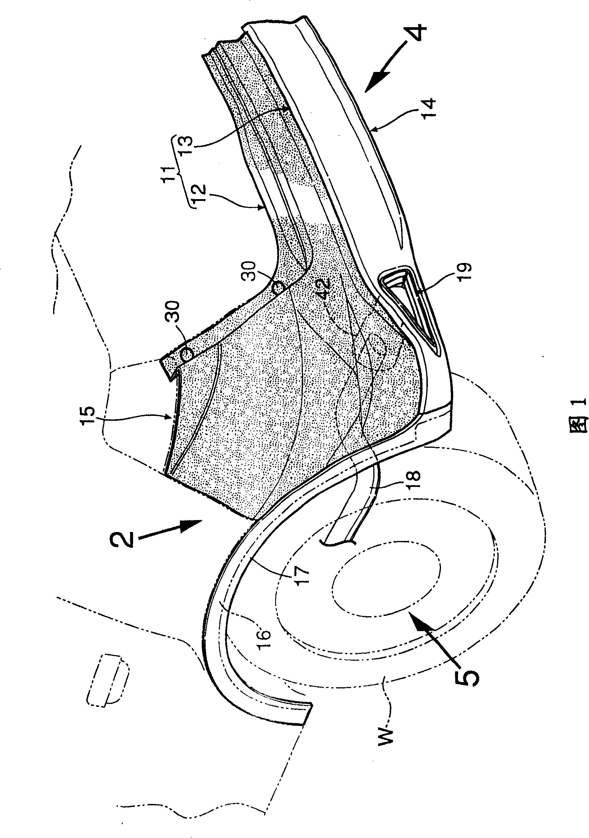
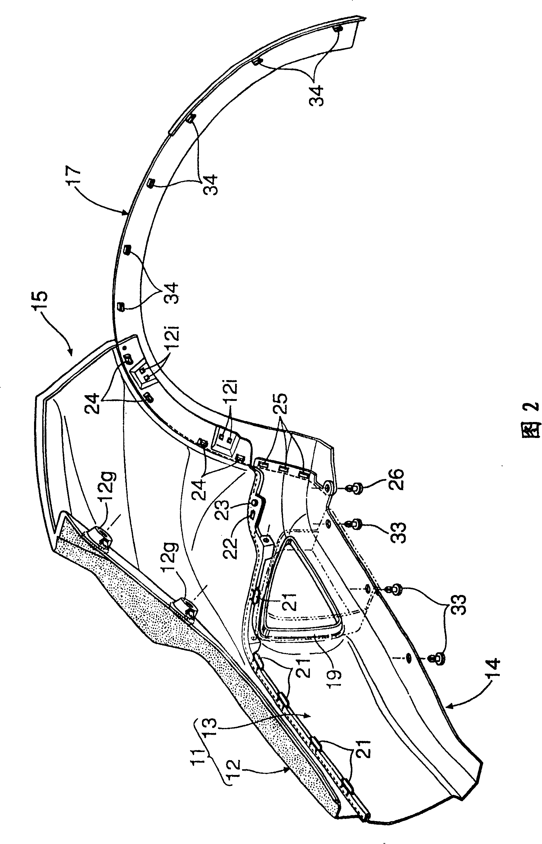
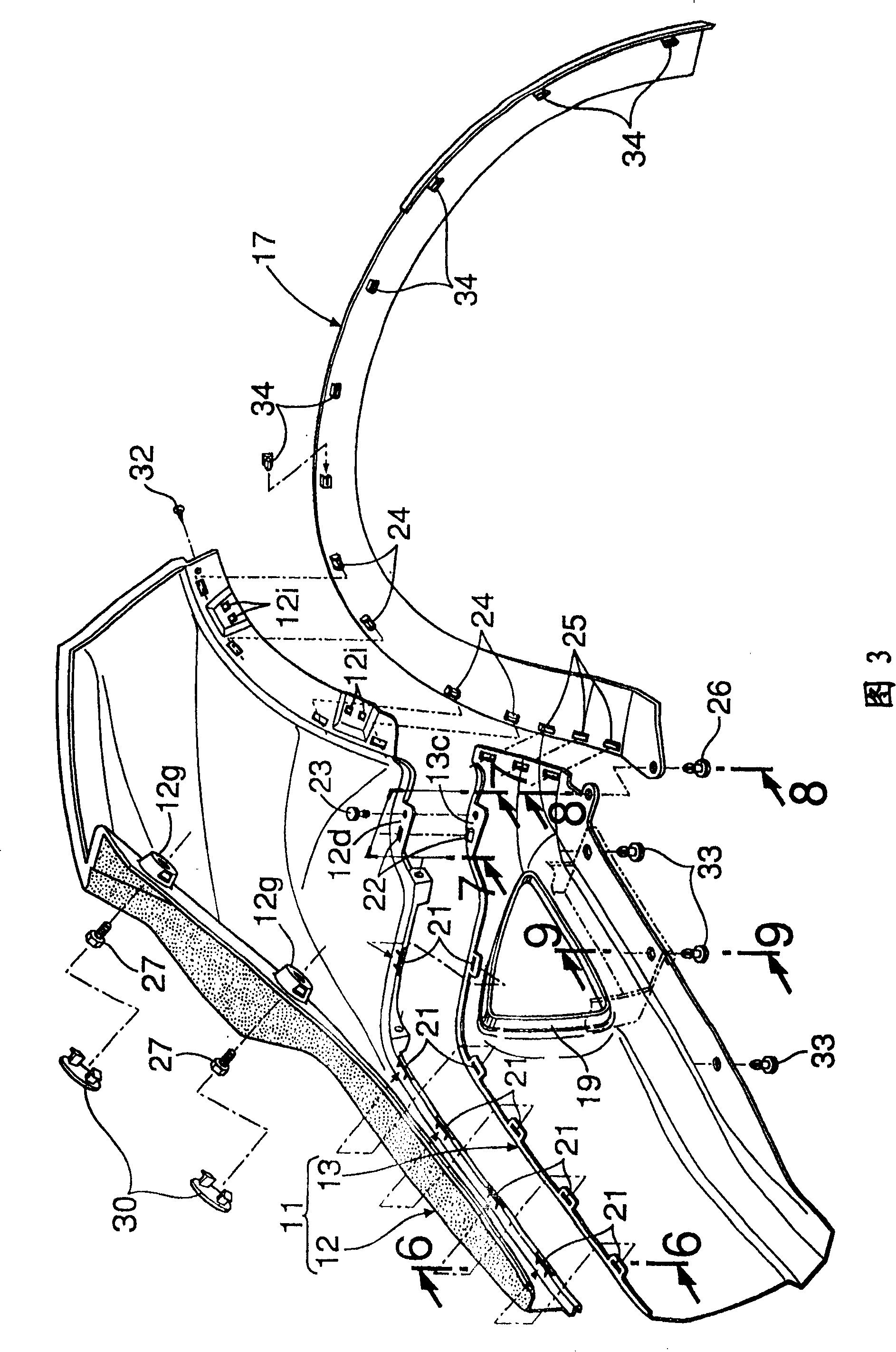
[0024] What Fig. 1~Fig. 15 showed is an embodiment of the present invention, and Fig. 1 is the perspective view of the left half of rear bumper. FIG. 2 is a view of arrow 2 in FIG. 1 . FIG. 3 is an exploded perspective view corresponding to FIG. 2 . FIG. 4 is a view of arrow 4 in FIG. 1 . FIG. 5 is a view from the arrow 5 in FIG. 1 . Figure 6 It is an enlarged sectional view taken along line 6-6 in FIG. 3 . Figure 7 It is an enlarged sectional view taken along line 7-7 in FIG. 3 . Figure 8 It is an enlarged sectional view taken along line 8-8 in FIG. 3 . Figure 9 It is an enlarged sectional view taken along line 9-9 in FIG. 3 . Figure 10 It is an enlarged sectional view taken along line 10-10 in FIG. 4 . Figure 11 It is an enlarged sectional view of each part in FIG. 5 . Figure 12 It is a schematic diagram of the effect of...


PUM


Abstract

The object of the present invention is to fix a wheel arch molding to a wheel arch beautifully so that a gap is not generated between the wheel archmolding and the wheel arch while decreasing a dimension in the vehicle width direction of the wheel arch molding that is fixed to the wheel arch of the bumper. In a structure for fixing a wheel arch molding, a radially outer edge of the wheel arch molding 17 is caused to abut on a step portion 16a formed at a radially outer edge of the wheel arch 16, and a clip 24 provided on a back surface of the wheel arch molding 17 at an intermediate portion in a band width direction is engaged with the wheel arch 16, whereby a protruding portion 16b formed at a radially inner edge of the wheel arch 16 presses the back surface of the wheel arch molding 17. Therefore, the radially outer edge of the wheel arch molding 17 closely contacts the step portion 16a to improve the appearance. In addition, a flange which protrudes inward in the vehicle width direction does not need to be formed at a radially inner edge of the wheel arch molding 17, so that a dimension in the vehicle width direction of the wheel arch molding 17 is made small to be able to secure a tread of a wheel.

Description

technical field [0001] The present invention relates to a fixing structure of a wheel mouth molding by which the wheel mouth molding is fixed to an arc-shaped wheel mouth formed on a bumper. Background technique [0002] Japanese Patent Application Publication No. 2000-103364 discloses the following technical scheme: the wheel mouth molding 5 installed on the wheel mouth (mounting surface 9) of the bumper flank 3 is made into an L-shaped section, so that the wheel mouth molding 5 arranged on the The protruding claws 16 on the inner surface of the decorative surface facing the outside of the vehicle body are engaged in the mounting holes 25 provided on the mounting surface 9 of the bumper wing 3, and the flange extending from the decorative surface inside the vehicle body (The contact surface 13 ) is fixed on the installation surface 12 of the bumper side wing 3 with the staple 15 . [0003] However, in the technical solution described in the above-mentioned Japanese Patent ...

Claims


Application Information

Patent Timeline
Patent Type & Authority Patents(China)
IPC IPC(8): B60R13/04F16B17/00
CPCB60R13/04B62D25/18B62D25/161
Inventor 籾井基之
Owner HONDA MOTOR CO LTD
Why Eureka
Try Eureka