Front-enclosed pressure balance type vale and its operating method

A closed pressure, balanced technology, applied in the direction of lift valve, valve device, engine components, etc., can solve the problem of large starting driving force, and achieve the effect of small sliding friction, small opening resistance and good sealing effect.

Inactive Publication Date: 2008-10-08
陆健
View PDF4 Cites 0 Cited by
  • Summary
  • Abstract
  • Description
  • Claims
  • Application Information

AI Technical Summary

Problems solved by technology

[0003] In order to overcome the problem of large start-up driving force existing in the existing valves, the present invention provides a front-closed pressure-balanced valve and its working method, which requires little driving force to open or close the valve.

Method used


Image

  • Front-enclosed pressure balance type vale and its operating method
  • Front-enclosed pressure balance type vale and its operating method
  • Front-enclosed pressure balance type vale and its operating method

Examples


Embodiment 1

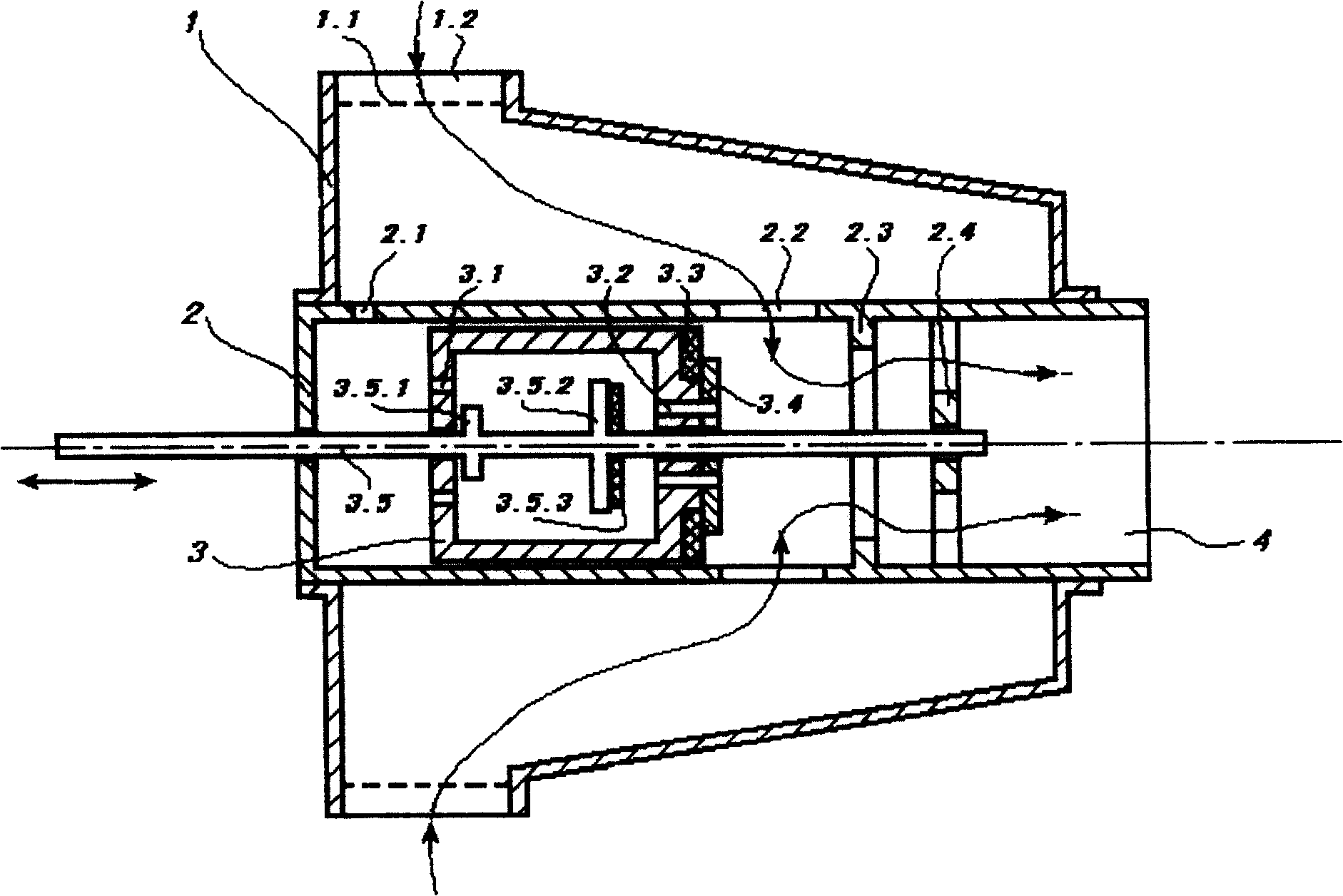
[0036] Front closed pressure balanced valves, such as figure 1 As shown, it includes a valve body shell 1, a valve core sleeve 2, a valve core 3, a power unit and a transmission device.

[0037] A water inlet 1.2 is arranged on the valve body shell 1, and a filter screen 1.1 is arranged on the water inlet 1.2.

[0038] The valve core sleeve 2 is placed in the valve body shell 1 and is in the shape of a sleeve. The spool cover 2 has a bottom wall, a peripheral side wall extending forward from the periphery of the bottom wall and a positioning frame 2.4. Two water inlets 2.2 are symmetrically opened on the peripheral side wall, and both water inlets 2.2 are in the fluid contained in the casing 1 . One or more water inlets 2.2 can also be provided on the peripheral side wall of the valve core sleeve 2 as required, and the multiple water inlets 2.2 are preferably evenly distributed, so that: when the valve core 3 moves to a position corresponding to the water inlet 2.2 When the...

Embodiment 2

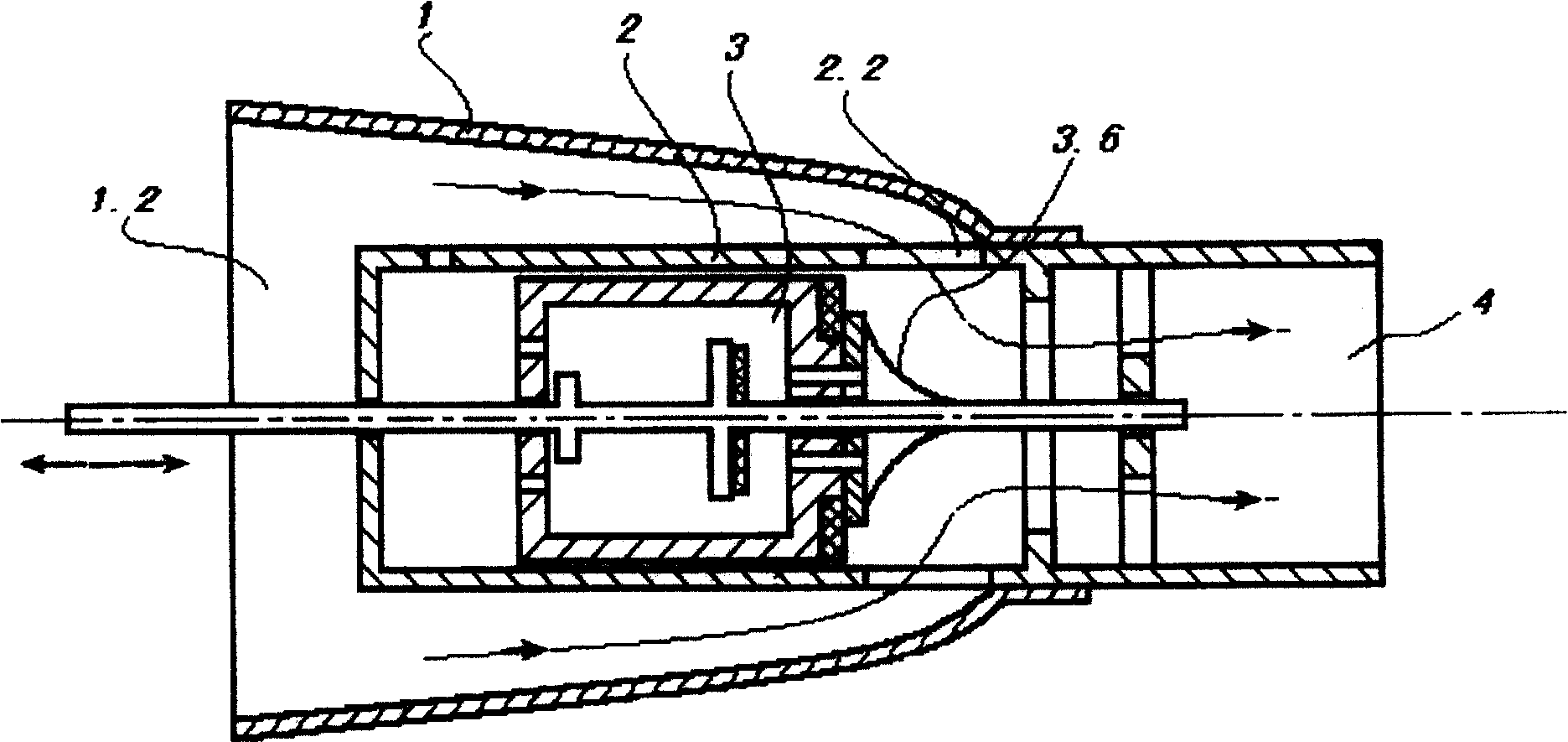
[0051] The difference between this embodiment and Embodiment 1 is that: figure 2 As shown, in a low flow resistance application mode, the front end of the valve core 3 has a deflector 3.6. The shell 1 of valve, spool cover 2, spool cover water inlet 2.2 and the guide plate 3.6 of spool front end, constitute the little streamline channel of fluid flow deflection angle, its water inlet is 1.2, and water outlet is 4.

Embodiment 3

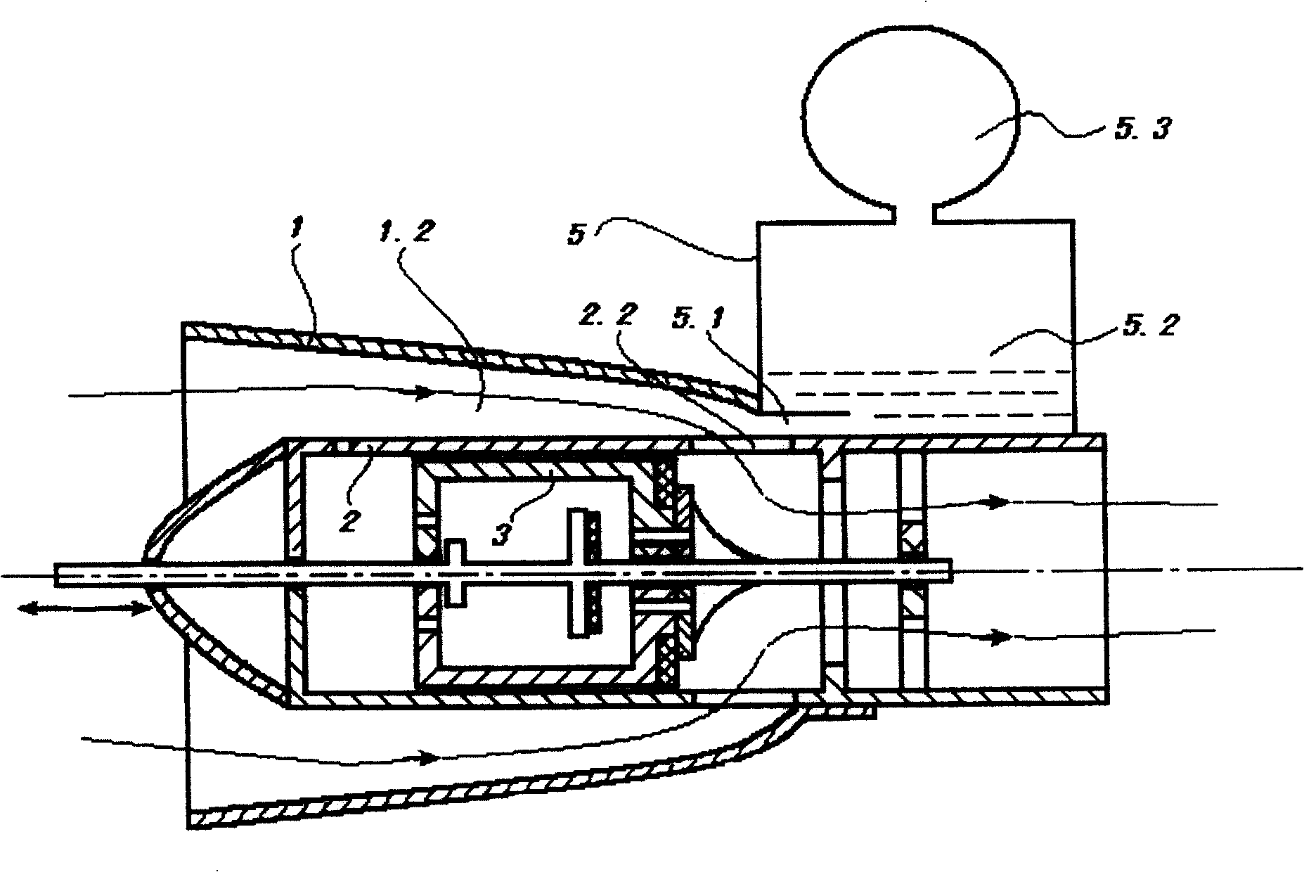
[0053] The difference between this embodiment and Embodiment 1 is that: image 3 As shown, the end of the water inlet 1.2 of the valve body shell 1 is provided with a swirl air buffer tank 5, which includes a swirl chamber 5.2 at the low end and an air chamber 5.3 at the high end. The swirl chamber is circular in cross section The cylindrical cavity, its water inlet 5.1 communicates with the water inlet 1.2 of the valve casing, and the water inlet 5.1 points to the tangential direction along the cylindrical surface of the cyclone chamber cylindrical cavity. When the water inlet 2.2 is closed by the valve core 3, the water flow enters the swirl chamber from the water inlet 5.1, the water flow rotates, the water level rises to compress the air, and the water hammer phenomenon is weakened.

[0054] The difference between this embodiment and Embodiment 1 is that: Figure 4 As shown, a water inlet of the valve of the present invention is an open application situation. There are t...


PUM


Abstract

The invention discloses a pressure-balance valve with closed frontal end and the working method. The valve comprises a valve core casing with inlet and outlet; valve core sliding in the valve core casing, which comprises base body, frontal sealing chip on the front of base body, drainage channel, by which frontal and back ends of valve core is connected and seal gasket closing the drainage channel, outlet closure formed by frontal sealing chip and seal gasket matched; a power device and a driving device. The closed process is that after drainage channel is closed valve core slides ahead to close the outlet and the connecting process is that after drainage channel is opened valve core slides backward to connect inlet and outlet. Thereout, driving force for opening and closing valve in the invention is small.

Description

technical field [0001] The invention relates to a valve, in particular to a front-end closed pressure-balanced valve and a working method thereof. Background technique [0002] At present, valves with larger diameters generally include two types, one is butterfly valves, ball valves, gate valves and other valves, and the other is mud discharge valves or globe valves. For butterfly valves, ball valves, gate valves and other valves with large diameters, the cooperation between the movable parts and the fixed parts is relatively tight, resulting in a large driving force required to open or close the valve, and multiple opening and closing are easy to cause wear between parts. Mud discharge valve or stop valve relies on the linear translation of the valve plate to cover the fluid channel to achieve the purpose of opening and closing the valve. The valve plate of this type of valve is subject to a large pressure in one direction of the fluid, and the driving force required to ope...

Claims


Application Information

Patent Timeline
Patent Type & Authority Patents(China)
IPC IPC(8): F16K1/00
Inventor 陆健
Owner 陆健
Why Eureka
Try Eureka