An adjustable oil mist separator welding mechanism

An oil mist separator and welding mechanism technology, applied in welding equipment, welding equipment, auxiliary welding equipment, etc., can solve problems such as welding quality decline, cylinder port wear, piston rod bending, etc., to ensure that the welding amount remains unchanged, Ensure the welding quality and avoid the effect of lateral bending

Active Publication Date: 2022-05-31
放骋智能科技(上海)有限公司
View PDF0 Cites 0 Cited by
  • Summary
  • Abstract
  • Description
  • Claims
  • Application Information

AI Technical Summary

Problems solved by technology

The oil mist separator needs to use welding technology in the process of processing. The existing welding mechanism is to adjust the adjustment plate after pulling the support rod through the movement of the piston rod in the cylinder, and then change the distance between the adjustment plates. Adapt to workpieces of different sizes. Since the piston rod pulls the support rod, the support rod will also exert tension on the piston rod, causing the piston rod to squeeze the cylinder mouth. Long-term extrusion will cause the cylinder mouth to wear, and will also make the piston The rod is bent under the influence of tension. At the same time, the welding process uses heating, high temperature or high pressure to partially melt the workpiece to form a molten pool, so that the workpiece partially forms a liquid metal. Due to the high fluidity of the liquid, it may occur during the welding process. As a result, the liquid metal flows to other areas under the influence of gravity, resulting in less liquid metal in the welding area, and the welding quality decreases after the welding is cooled and solidified.

Method used


Image

  • An adjustable oil mist separator welding mechanism
  • An adjustable oil mist separator welding mechanism
  • An adjustable oil mist separator welding mechanism

Examples


Embodiment Construction

[0020] The technical solutions in the embodiments of the present invention will be clearly and completely described below with reference to the accompanying drawings in the embodiments of the present invention. Obviously, the described embodiments are only a part of the embodiments of the present invention, but not all of the embodiments. Based on the embodiments of the present invention, all other embodiments obtained by those of ordinary skill in the art without creative efforts shall fall within the protection scope of the present invention.

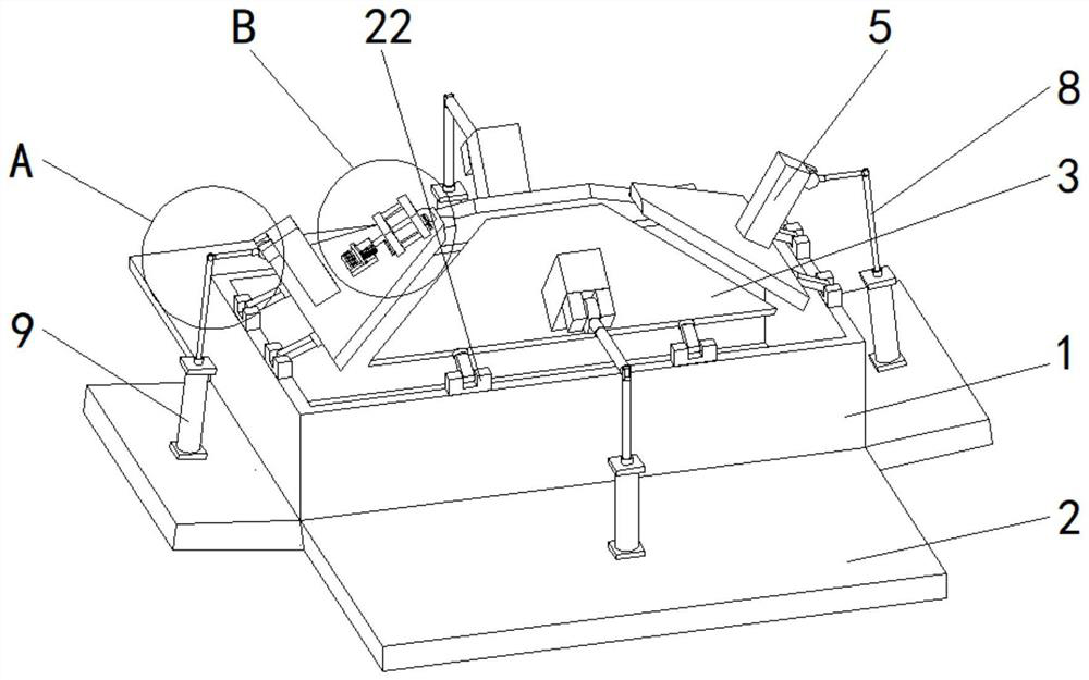
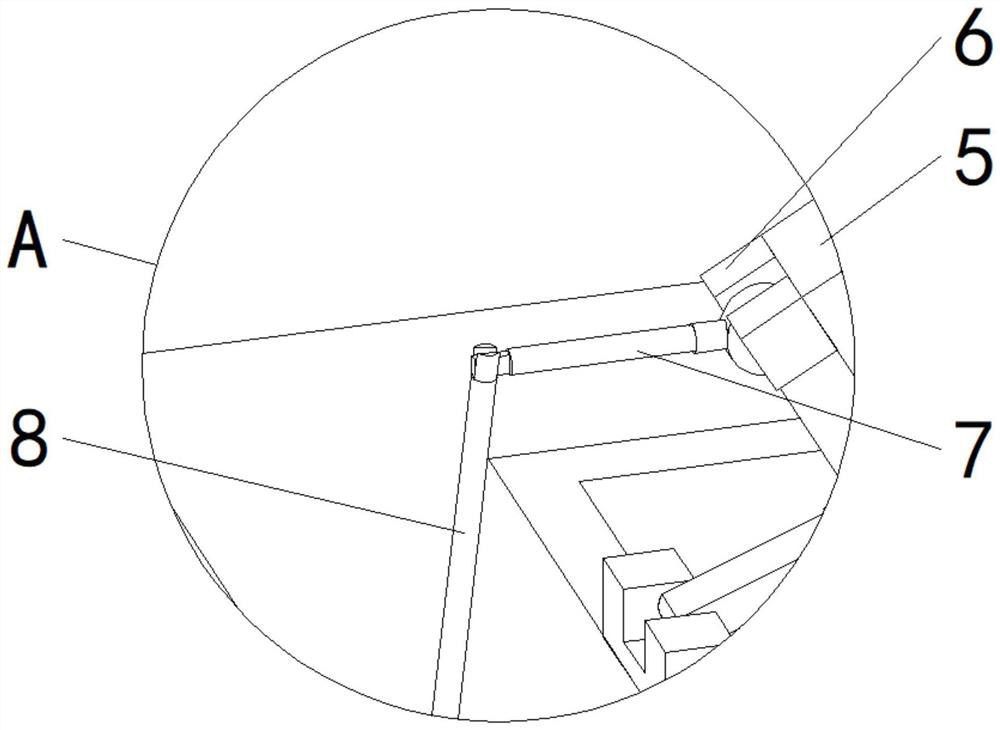
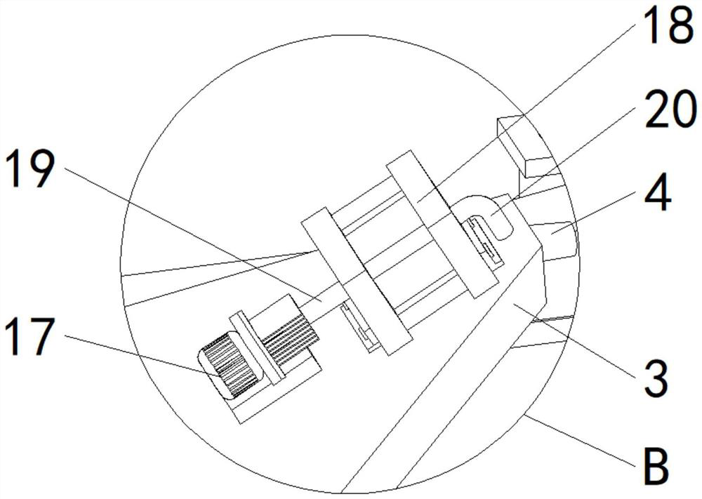
[0021] see Figure 1-8 , including the base 1, the support plate 2 and the adjustment plate 3, the top of the base 1 is a square ring, the top of the base 1 is fixedly installed with a rotating mechanism 22, and the number of the rotating mechanism 22 is eight, the bottom of each adjustment plate 3 There are two installed to reduce the force of a single rotating mechanism 22 and prolong the service life of the rotating mechanism 22. T...


PUM


Abstract

The invention relates to the technical field of oil mist separator welding mechanism, and discloses an adjustable oil mist separator welding mechanism, including a base, a support plate and an adjustment plate, the number of the support plate and the adjustment plate are four, four The four supporting plates are respectively fixedly installed on the side of the base, the four adjusting plates are respectively rotatably installed on the top of the base, and one side of the four adjusting plates is fixedly installed with a welding head. The tops of the adjusting plates are all fixedly equipped with supporting columns, one side of the four supporting columns is fixedly installed with connecting pieces, one side of the four described connecting pieces is all rotatably installed with connecting rods, and the connecting rods A piston rod is rotatably installed at one end. The welding mechanism of the adjustable oil mist separator, when the force is applied by the connecting rod, the angle between the piston rod and the piston rod is 90 degrees, so that the oblique force of the piston rod becomes vertical force, so the lateral force of the piston rod can be reduced. force to avoid lateral bending of the piston rod.

Description

technical field [0001] The invention relates to the technical field of welding mechanisms for oil mist separators, in particular to an adjustment type welding mechanism for oil mist separators. Background technique [0002] The oil mist separator is a kind of equipment installed on CNC machining centers, cleaning machines, die casting machines or CNC lathes, etc., to absorb the oil mist in the processing cavity, to purify the air and protect the health of workers. The oil mist separator needs to use a welding process in the processing process. An existing welding mechanism uses the movement of the piston rod in the cylinder to adjust the adjustment plate after pulling the support rod, thereby changing the distance between the adjustment plates. It is suitable for workpieces of different sizes. When the piston rod pulls the support rod, the support rod will also exert a pulling force on the piston rod, causing the piston rod to squeeze the cylinder port of the cylinder. Long-...

Claims


Application Information

Patent Timeline
Patent Type & Authority Patents(China)
IPC IPC(8): B23K31/02B23K37/00B23K37/04
CPCB23K31/02B23K37/00B23K37/04Y02P70/10
Inventor 万婧
Owner 放骋智能科技(上海)有限公司
Why Eureka
Try Eureka