

Safety cord release of window covering
- Summary
- Abstract
- Description
- Claims
- Application Information
AI Technical Summary
Benefits of technology
Problems solved by technology
Method used
Image

Examples
Embodiment Construction
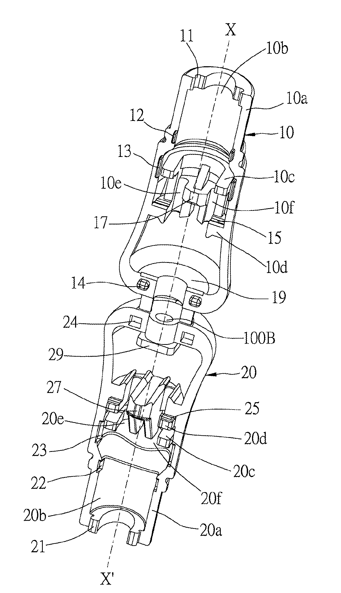
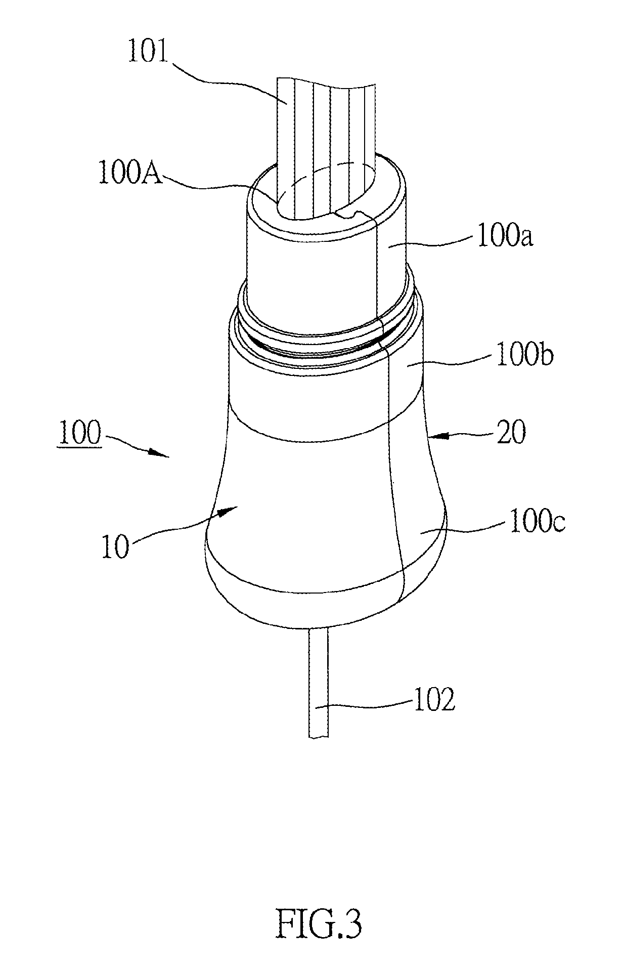
[0019]A safety cord release 100 of the preferred embodiment of the present invention includes a right case 10 and a symmetrical left case 20 connected together to form a barrel with a top opening 100A and a bottom opening 100B. Two connecting pieces 30 connect bottoms of the right case 10 and the left case 20. Cords 101 may be inserted into the safety cord release 100 via the top opening 100A, and an operating cord 102 may be inserted into the safety cord release 100 via the bottom opening 100B. The left case 20 has a plate 29 at the bottom thereof, and the bottom opening 100B is provided through the plate 29. The plate 29 touches and sits on an inner side 19 of the bottom of the right case 10 when the cord release is in the closed position, as shown in FIG. 7.
[0020]The right case 10 and the left case 20 each has an edge 10a(20a) with a recess 10b(20b) thereon, and a top cord fastener 10c(20c) and a bottom cord fastener 10d(20d) projected from an inner sidewall of the recess 10b(20b...
PUM
 Abstract
Description
Claims
Application Information