Dynamic operator functions based on operator position

An operator and capability technology, applied in the field of communication systems, which can solve the problems of overloading the central process control system, economic infeasibility, complex process and system, etc., to achieve the effect of shortening time

Inactive Publication Date: 2008-11-26
ABB (SCHWEIZ) AG
View PDF7 Cites 0 Cited by
  • Summary
  • Abstract
  • Description
  • Claims
  • Application Information

AI Technical Summary

Problems solved by technology

The first disadvantage is that one terminal must be provided for each machine to be monitored; therefore, thousands of such terminals are required, making the whole solution economically unviable (especially if the terminals are only infrequent inspection)
The second major disadvantage is that the terminal must query the central process control system multiple times in order to obtain information from other machinery or connected systems; a large number of such queries would then overload the central process control system
[0014] Processes and systems in manufacturing or processing plants are becoming increasingly complex
For these systems, status information is often very complex, but still must be interpreted in a short time

Method used


Image

  • Dynamic operator functions based on operator position
  • Dynamic operator functions based on operator position
  • Dynamic operator functions based on operator position

Examples


Embodiment Construction

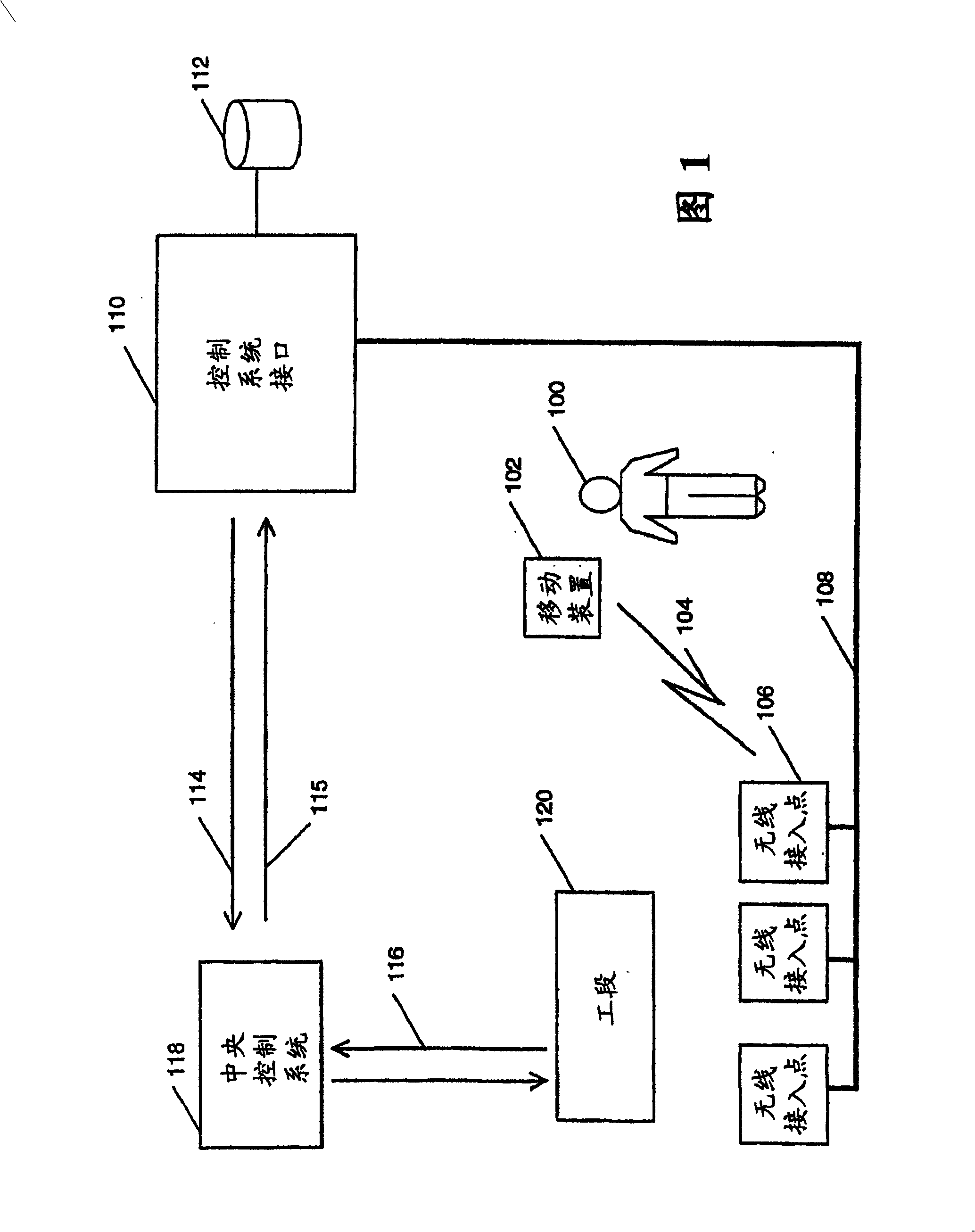
[0034] Figure 1 is a block diagram showing operators who remotely access various sections of an industrial factory. A manufacturing or processing plant contains many sections, and FIG. 1 shows one such section 120. The section may be a large section such as a production line, a bleaching plant or a paper machine, or a small section such as a single piece of equipment. There are many machines and / or subsystems in the work section 120, which are connected to each other to perform a specific process. Most industries have a centralized control system 118 for controlling and monitoring the work section 120. The centralized control system 118 coordinates and controls different sections 120 through a data network. The data network is usually a wired LAN that connects each section to the centralized control system 118. The centralized control system 118 receives status information from each work section 120, and sends control instructions for the work section through the data network. The...


PUM


Abstract

A communication system that enables an operator to remotely query and control the process sections in an industrial plant by exchanging data with a central computer that controls the process sections. The operator communicates with the process sections through a mobile wireless device remotely connected with one of the multiple wireless access points on a data network. This data network is, in turn, connected to the central computer that controls these process sections. The central computer stores the location of the process sections and the operator profiles. When requested, it collates and processes this data and presents it to the operator. Further, if the need arises, the central computer tracks and interacts with the operator.

Description

Technical field [0001] The present invention relates to a communication system, an industrial control system, a method, and a computer program product, and the above-mentioned system, method, and product provide an operator with a means to query and control work sections in an industrial factory. Background technique [0002] The manufacturing and processing industries have become very complex in recent decades. Today, even small manufacturing plants can easily contain hundreds or even thousands of manufacturing and processing machinery. These machines are generally intricately connected to each other to form a sub-system, and the sub-systems themselves are connected to form a larger system, and so on, until they form the entire factory together. Since these individual machines are so intricately connected, a small change in the output of one machine (or a piece of equipment) may easily cause another machine to malfunction, and even make the final product unacceptable. Therefore,...

Claims


Application Information

Patent Timeline
Patent Type & Authority Patents(China)
IPC IPC(8): G05B19/18G08C17/02H04L12/26H04L12/28H04L12/56H04L29/08
CPCH04W84/22H04W4/028G05B2219/31162H04L67/12H04W84/00H04L29/08558H04L29/08072H04W4/02H04W88/08H04L29/08657H04L69/329H04L67/18H04W84/12H04W4/029H04L67/52
Inventor P·厄贝里J·-E·弗雷
Owner ABB (SCHWEIZ) AG
Why Eureka
Try Eureka