Method and controller for inhibiting transformer dc magnetic bias

A transformer and controller technology, which is applied to the conversion equipment with intermediate conversion to AC, the conversion of AC power input to DC power output, and the conversion of irreversible DC power input to AC power output, etc., can solve the problem of increasing the excitation current of the transformer. , the increase of primary copper loss of the transformer, the low efficiency of the converter, etc.

Inactive Publication Date: 2008-12-24
DELTA ELECTRONICS INC
View PDF4 Cites 0 Cited by
  • Summary
  • Abstract
  • Description
  • Claims
  • Application Information

AI Technical Summary

Problems solved by technology

However, the introduction of the air gap in this scheme will reduce the excitation inductance of the transformer, thereby increasing the excitation current in the transformer
This results in increased copper losses in the transformer primary, which is equivalent to an increase in the AC impedance of the transformer primary winding
Ultimately, the efficiency of the converter is not high
It can be seen that a small air gap is required for high efficiency, but a small air gap will make the transformer more prone to saturation

Method used


Image

  • Method and controller for inhibiting transformer dc magnetic bias
  • Method and controller for inhibiting transformer dc magnetic bias
  • Method and controller for inhibiting transformer dc magnetic bias

Examples


Embodiment Construction

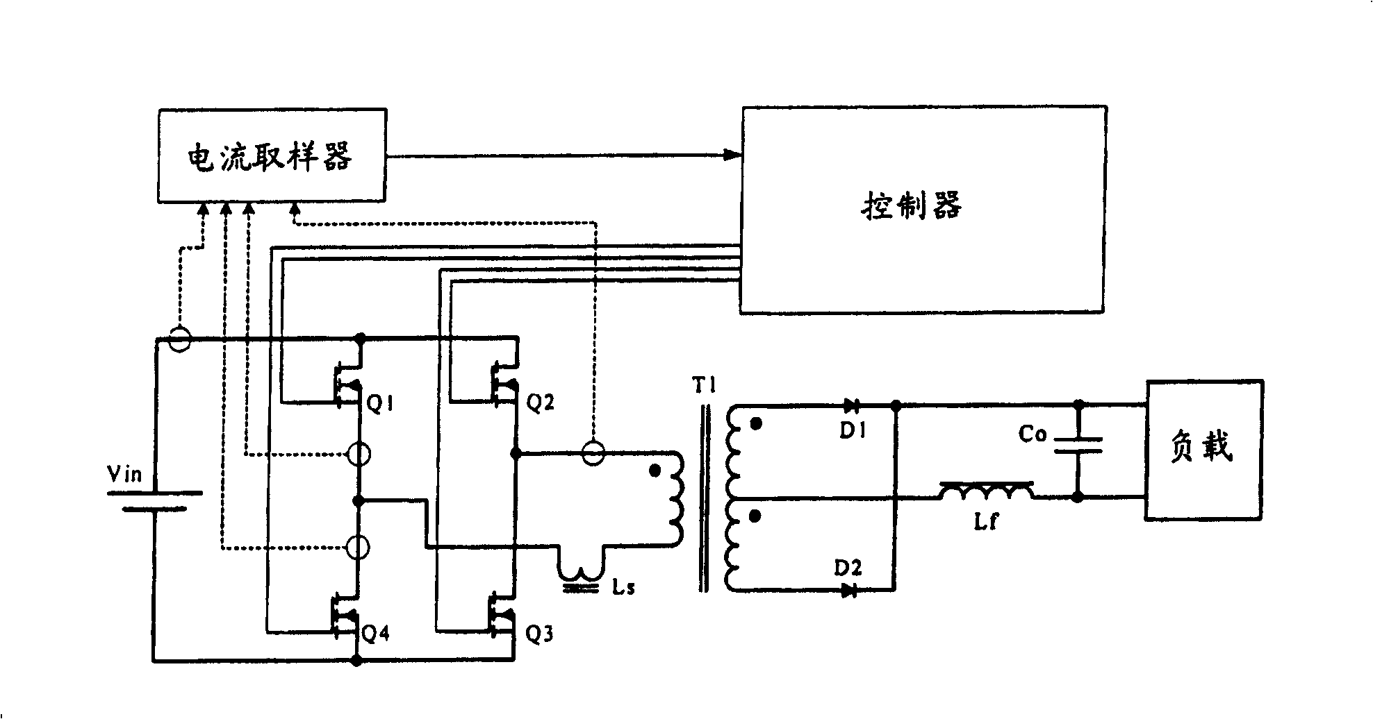
[0031] The principle of the present invention is to obtain the DC component signal corresponding to the primary of the transformer through transient current detection, and through fast processing, the duty ratio of the power switching element is transiently adjusted, thereby suppressing the DC component of the transformer primary.

[0032] Principle of work of the present invention is analyzed as follows:

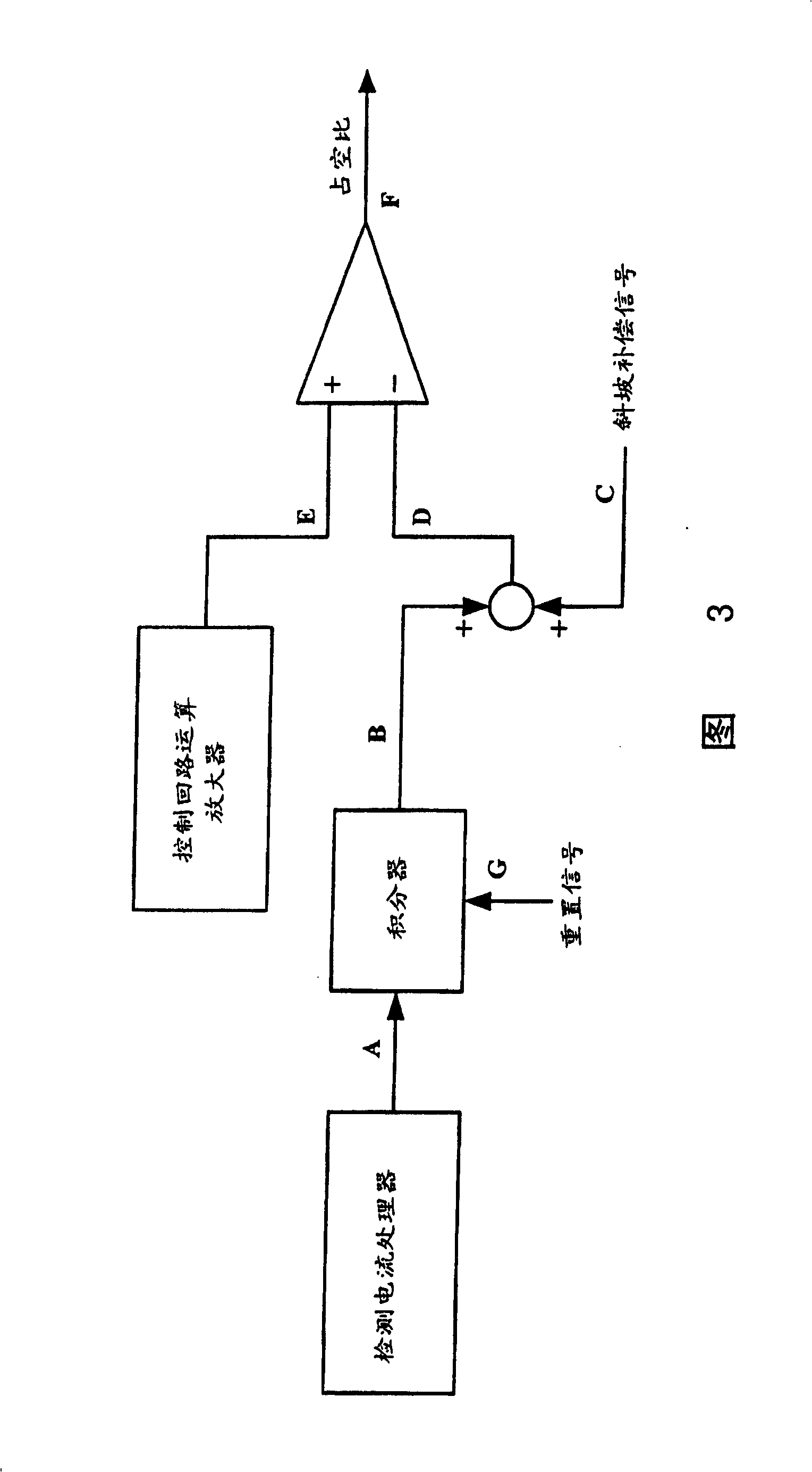
[0033] Fig. 3 is a block diagram of DC component suppression control in a preferred embodiment of the present invention. The signal A in the figure is the signal after the sampling result (or part of the sampling result) is preprocessed. It can basically reflect the positive and negative asymmetry of the primary current of the transformer. The B signal is the result of integrating the A signal. It is compared with the sum of the compensation signal C (D signal) and the error operational amplifier output E of the control loop of the traditional circuit. The comparator outpu...


PUM


Abstract

This invention puts forward a method and a system for suppressing DC bias of a transformer and a power converter using said method and system, the input end of which is a full bridge structure, its output is a full wave commutation unit, energy is delivered from the input to the output via the transformer. The system includes: 1. a current sampling unit used in collecting the primary DC component of the transformer, 2. a controller connected with a current sampling unit which regulates work of the master circuit power switch element according to current samplings so as to suppress DC bias of the transformer.

Description

(1) Technical field [0001] The invention generally relates to the field of power conversion, in particular to a system that needs to suppress the DC magnetic bias of a power transformer, and a converter using the system and method. (2) Background technology [0002] Power conversion circuits often convert a specific input voltage waveform into a specified output voltage waveform. In many applications, it is necessary to convert an input DC voltage into a required output DC voltage, which may be higher or lower than the input voltage. Typical applications of this type of converter are communication power supplies and computer power supplies. [0003] A full-bridge circuit structure system commonly used in current converters (such as figure 1 As shown), it uses four controllable power switching elements (Q1~Q4, usually MOSFET), a power transformer (T1, usually isolation transformer), output rectifier unit and output filter (Lf and Co). Of course there is also a controller f...

Claims


Application Information

Patent Timeline
Patent Type & Authority Patents(China)
IPC IPC(8): H02M3/28H02M7/48H02M7/5387
Inventor 刘腾郭兴宽应建平曾剑鸿
Owner DELTA ELECTRONICS INC
Why Eureka
Try Eureka