


Quick Research
Generate reliable direction feasibility study reports for your R&D in just a few steps.

Technical Q&A
Discover and master advanced knowledge NOW. Basics, ideas, possibilities, all at once.

Find Solutions
As an expert in R&D theories, this can generate solutions to your technical problems instantly.

Evaluate Feasibility
Analyze your overall solution with one click, know your potential R&D risks in advance.

Monitor Landscape
Get weekly tech updates, stay abreast of the latest tech innovations and key insights.
Heat radiator and its producing method
一种散热翅片、制造方法的技术,应用在散热器的制造及散热翅片的形成领域,能够解决作业人员受伤、元件损伤等问题,达到提高商品价值、预防损伤、提高散热效果的效果
- Summary
- Abstract
- Description
- Claims
- Application Information
AI Technical Summary
Problems solved by technology
Method used
Image

Examples
Embodiment 1
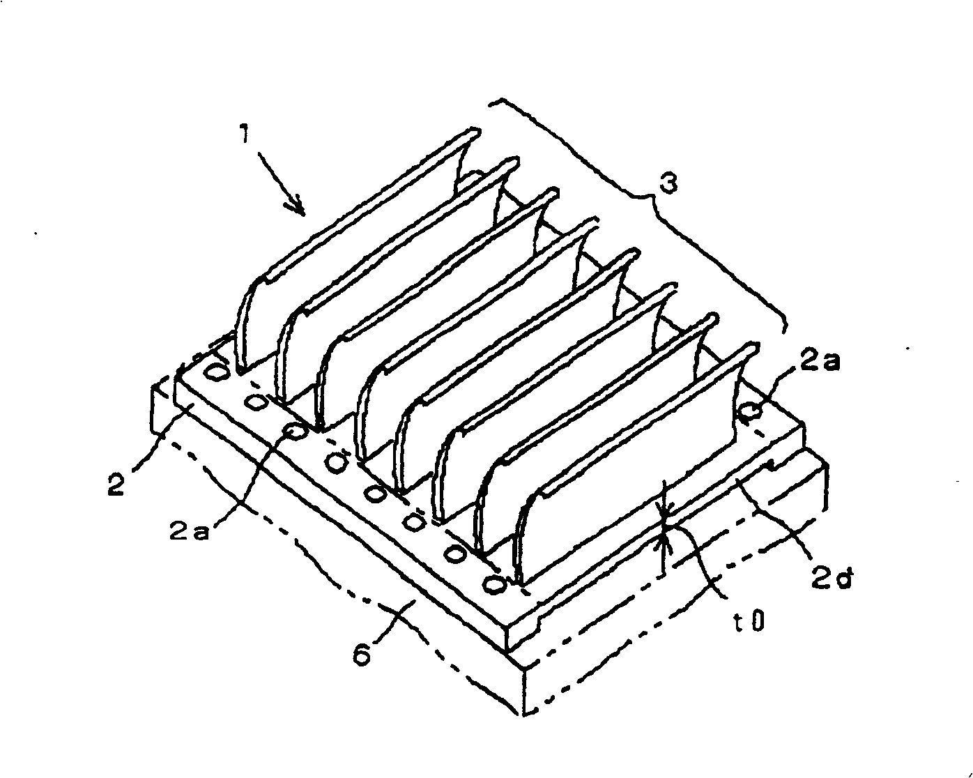
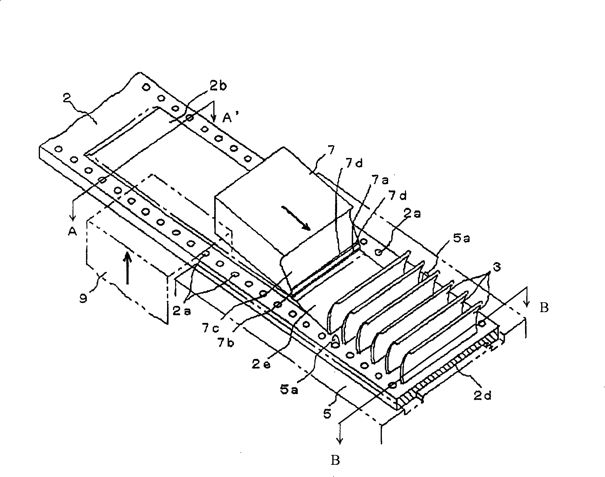
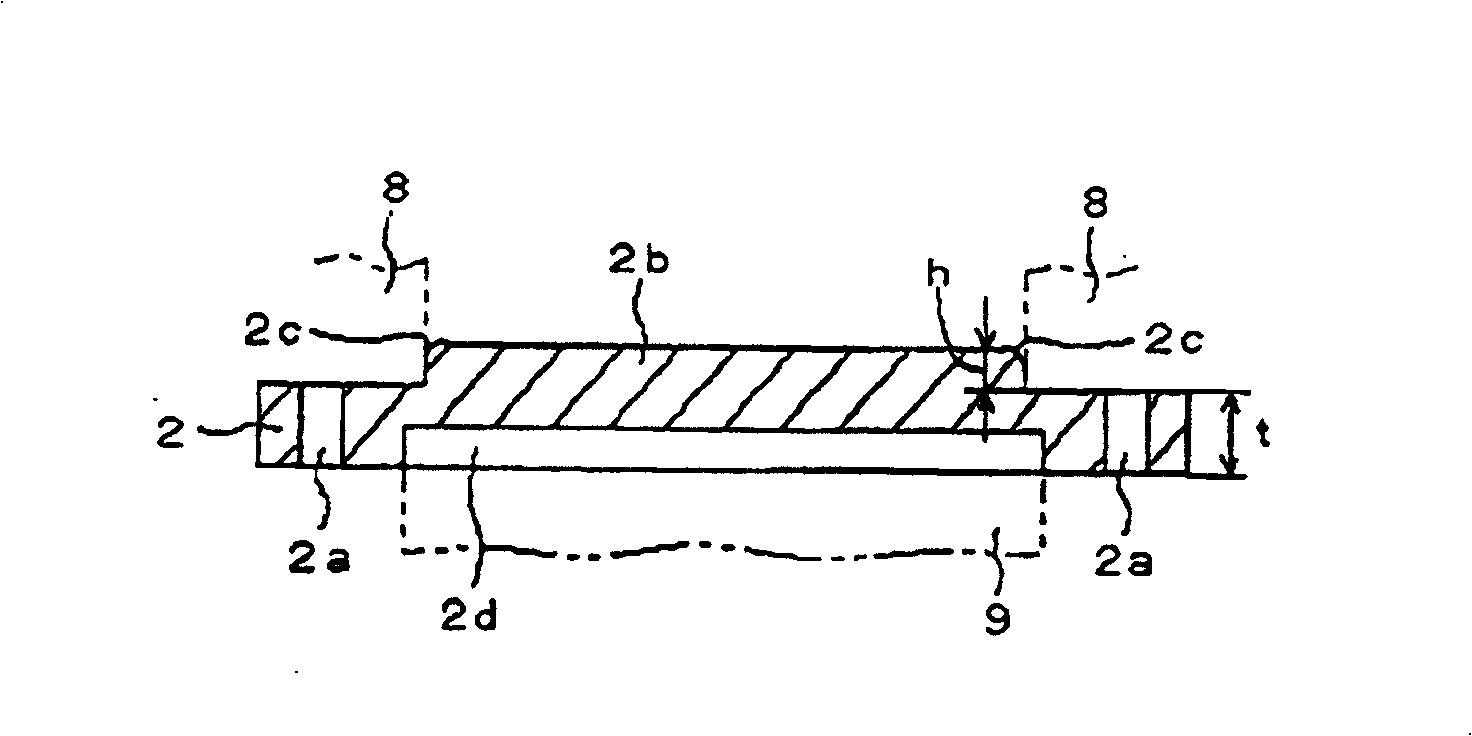
[0056] figure 1 It is a perspective view showing the radiator of Embodiment 1 of the present invention, figure 2 yes means figure 1 perspective view of the manufacturing method of the heat sink, image 3 It is a sectional view showing the part cut by the A-A line. The metal material used in the heat sink of this example can be processed plastically and is a metal material with good heat transfer coefficient. For example, a metal plate having a predetermined thickness is used, which is formed of a material such as aluminum, aluminum alloy, copper alloy, or stainless steel.
[0057] The heat sink 1 of this example is composed of a metal plate 2 and a plurality of fins 3 integrally formed on the surface. Each heat dissipation fin 3 extends parallel to the short-side direction of the metal plate 2 . In addition, these plural fins 3 protrude at approximately the same angle, and are formed in parallel at approximately the same intervals. In addition, the heat radiation fin 3 ...
Embodiment 2
[0076] Figure 10 Example 2 of the present invention is shown, showing a method of increasing the surface area of the heat radiation fins formed on the heat sink. The planing tool 10 used in Example 2 is substantially the same as the planing tool 7 used in Example 1, except that a plurality of recesses 11 are formed on the edge portion 10a perpendicular to the moving direction at the front end on the bottom side. This planing tool 10 is formed with two slopes 10b, 10c inclined at a predetermined angle from the blade portion 10a, and a step portion 10d is formed between the two slopes 10b, 10c, which is different from the planing tool 7 shown in Embodiment 1. same.
[0077] Same as above-mentioned Embodiment 1, on the band-shaped metal plate 2 supplied sequentially from the supply device, a guide hole 2a having a function as a positioning and locking portion is formed, and the pushing tool is pushed from the other side of the band-shaped metal plate 2 simultaneously. 9 push...
Embodiment 3
[0081] Figure 11 Embodiment 3 of the present invention is shown, showing a heat sink manufacturing method in which a plurality of fin rows are simultaneously formed on a band-shaped metal plate 2 . The planing tool 20 used in this embodiment 3 is also substantially the same as the planing tool 7 used in embodiment 1, the difference is that, as Figure 11 As shown, a deep dividing groove 21 is formed in the center of the blade portion perpendicular to the moving direction at the front end on the bottom surface side, and the blade portion is divided into two to form a pair of blade portions 22,23. In addition, the planing tool 20 is formed with two inclined surfaces 22a, 22b and 23a, 23b inclined at a predetermined angle from the respective blade portions 22, 23, and a stepped portion 22c, 23c.
[0082] On the belt-shaped metal plate 2 sequentially supplied from the supply device, the guide hole 2a having the function of positioning and locking part is perforated, and the pre...
PUM
 Abstract
Description
Claims
Application Information
 - R&D Engineer
- R&D Manager
- IP Professional
- Industry Leading Data Capabilities
- Powerful AI technology
- Patent DNA Extraction
Browse by: Latest US Patents, China's latest patents, Technical Efficacy Thesaurus, Application Domain, Technology Topic, Popular Technical Reports.
© 2024 PatSnap. All rights reserved.Legal|Privacy policy|Modern Slavery Act Transparency Statement|Sitemap|About US| Contact US: help@patsnap.com