Laser circular cutting punching method and its device

A circumcision and laser technology, applied in laser welding equipment, welding equipment, metal processing equipment and other directions, can solve the problems of expensive equipment, low efficiency, complex technology, etc., and achieve the effect of simple and reliable device structure, low cost and high efficiency

Inactive Publication Date: 2009-02-04
武汉工研光学科学技术股份有限公司
View PDF7 Cites 0 Cited by
  • Summary
  • Abstract
  • Description
  • Claims
  • Application Information

AI Technical Summary

Problems solved by technology

However, the existing laser cutting machines are complex in technology, expensive in equipment, inefficient, and almost powerless to process micro-holes with smaller apertures
The deficiencies in the above aspects hinder the further development of laser microhole processing technology

Method used


Image

  • Laser circular cutting punching method and its device
  • Laser circular cutting punching method and its device
  • Laser circular cutting punching method and its device

Examples


Embodiment Construction

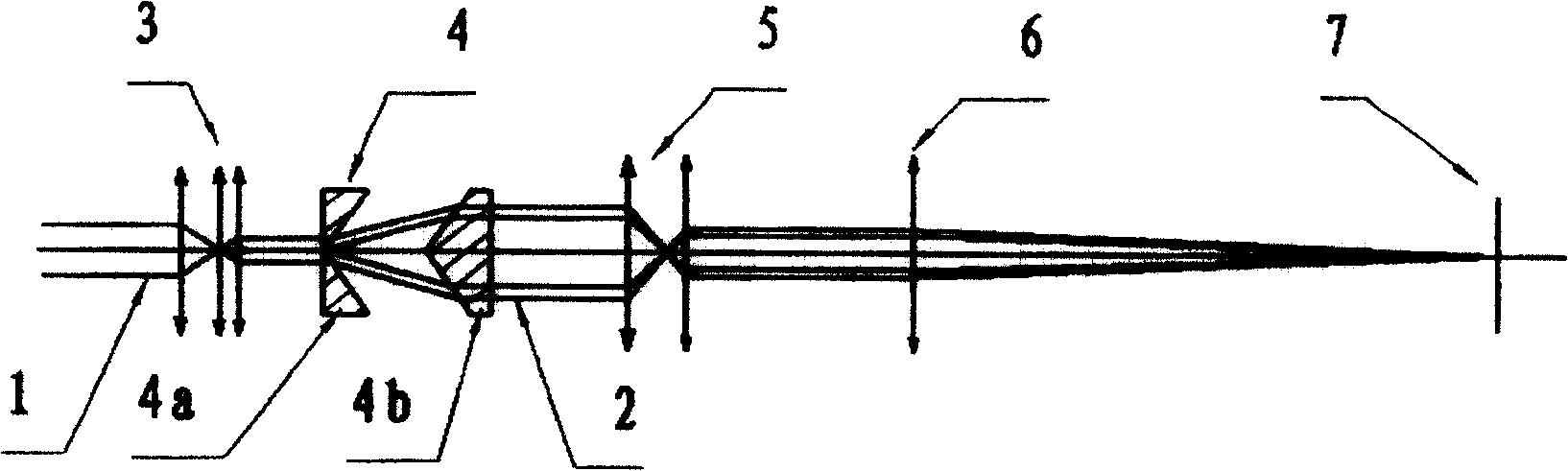
[0012] From figure 1 It can be known from the shown optical path principle of laser ring cutting and perforation that the laser beam 1 with a circular cross section is compressed by a beam compression device 3 and enters the light ring generator 4 . The halo generator 4 is composed of a pair of negative conical light wedges 4a and positive conical light wedges 4b that are relatively separated in space. The centers of the shaped laser beams 1 coincide, and the conical angles of the negative conical light wedge 4a and the positive conical light wedge 4b ​​should avoid total reflection. The circular laser beam 1 refracts and diverges through the negative cone light wedge 4a in the light ring generator 4, refracts and converges through the positive cone light wedge 4b, and outputs a collimated laser beam 2 with a circular cross-section. The laser beam 2 is then compressed and reduced by another beam compression device 5 into a thinner annular laser beam, and finally focused on th...


PUM


Abstract

The present invention discloses laser circular cutting punching method and device. The method includes converting circular laser beam into ring laser beam, focusing the ring laser beam, regulating the processed sheet to the focus and forming ring laser spot on the sheet to be processed so as to melt and gasify the sheet material forming hole through circular cutting. The device includes mainly laser, image lens, and laser ring generator set between the laser and the image lens. The laser ring generator consists of one pair of separated negative conic light wedge and positive conic light wedge, and is used to perform the said conversion. The present invention has the features of wide processing hole aperture range, easy regulation of processing hole aperture, high processing efficiency, low cost, etc.

Description

technical field [0001] The invention relates to laser drilling technology, in particular to a laser ring cutting and drilling method and its device, which are used for micro-hole processing of thin plates. Background technique [0002] It has a long history to apply laser drilling technology to the micro-hole processing of thin plates. However, the development of this technology has been relatively slow in recent years, and the difficult control of the machining aperture is one of its main technical difficulties. This is because: the transmission of the laser is carried out in a cylindrical shape in the space contained by its divergence angle, and it is a solid circular spot on the cross section perpendicular to the propagation direction of the laser beam, and its energy is distributed within the area of ​​the solid circle , the laser beam converges in a conical shape after being focused by the imaging lens, forming a focal point at the intersection. If the blasting effect...

Claims


Application Information

Patent Timeline
Patent Type & Authority Patents(China)
IPC IPC(8): B23K26/073B23K26/38B23K26/282
Inventor 钱惠国卢治石敏王晓晖万浩陈晓泉
Owner 武汉工研光学科学技术股份有限公司
Why Eureka
Try Eureka