Optic machine automatic fixing device of image scanning device

A fixed device, image scanning technology, applied in the direction of image communication, electrical components, etc., to achieve the effect of great convenience and comprehensive security protection

Active Publication Date: 2009-04-22
北京高德品创科技有限公司
View PDF4 Cites 0 Cited by
  • Summary
  • Abstract
  • Description
  • Claims
  • Application Information

AI Technical Summary

Problems solved by technology

[0005] However, the above-mentioned locking device must rely on human memory and manipulation. Once the user forgets to lock the locking device, when the scanning device is transported, the optical machine cannot avoid the situation of momentary vibration or collision. For high-precision image scanning devices, it is necessary to provide the function of automatically generating fixed photomechanics

Method used


Image

  • Optic machine automatic fixing device of image scanning device
  • Optic machine automatic fixing device of image scanning device
  • Optic machine automatic fixing device of image scanning device

Examples


Embodiment Construction

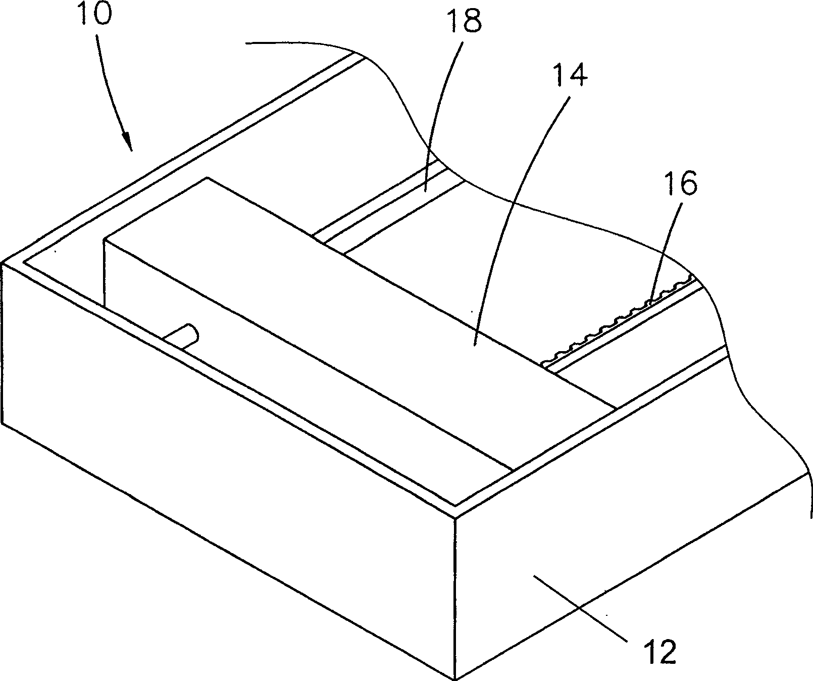
[0023] Such as figure 1 As shown, the figure discloses a partial assembly view of an image scanning device, such as a partial assembly appearance view of a scanner. The lower body 12 of the scanner 10 is equipped with an optical engine 14 , and the optical engine 14 is equipped with components such as a light source, a plurality of reflectors, and an image sensor. In addition, the optical machine 14 cooperates with the transmission belt 16 and can move back and forth along the guide rod 18 driven by the transmission belt 16 .

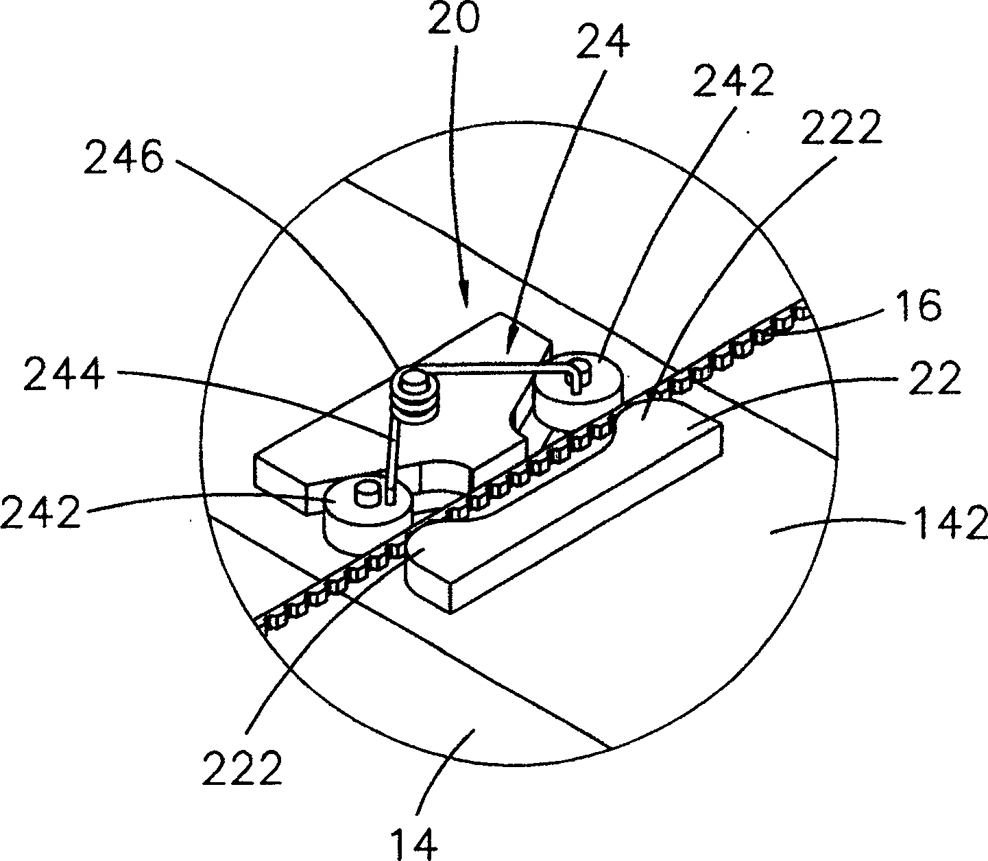
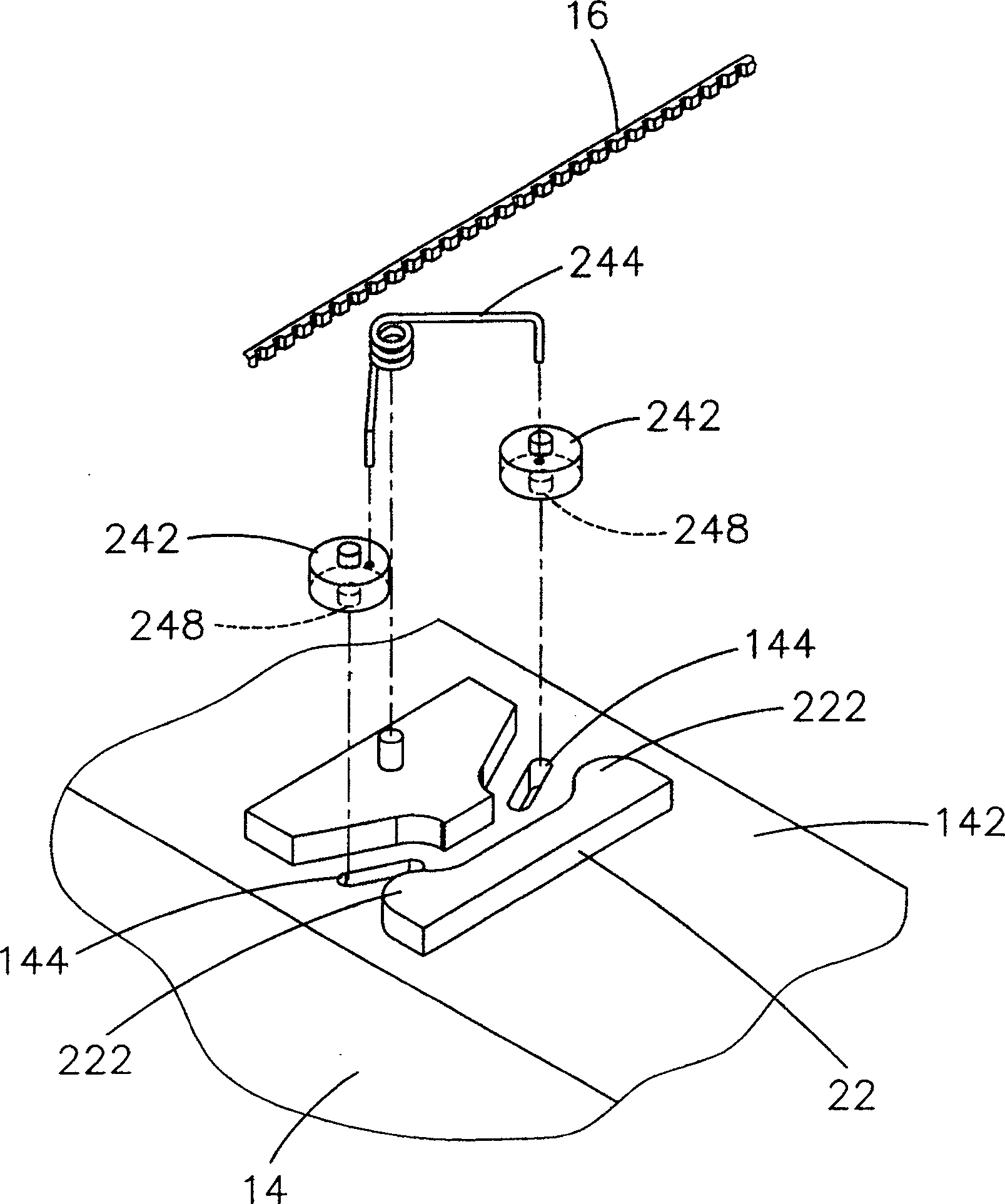
[0024] Such as figure 2 , 3 As shown, the present invention designs an optical-mechanical automatic fixing device 20 , which is arranged on the bottom surface 142 of the optical-mechanical device 14 . The optical machine automatic fixing device 20 includes a stop block 22, which is fixed on the bottom surface 142 of the optical machine 14, and is located on one side of the transmission belt 16, and the stop block 22 is on one side of the transmissio...


PUM


Abstract

An automatically fixing device set bottom surface of image scanning device contains stop block and clamping assembly, scanner moving driving belt set between stop block and clamping assembly, when aid scanner moving then clamping assembly clamping said driving belt to make positioning.

Description

technical field [0001] The present invention relates to an automatic fixing device, especially used in image scanning devices, such as flatbed scanners, sheet-fed scanners, copiers and the like. When the optical machine of the image scanning device is impacted, for example, when it is moved or shaken, the automatic fixing device can automatically clamp the belt connected to the optical machine so that the optical machine is fixed without momentary vibration. Background technique [0002] A general image scanning device, such as a scanner, is basically composed of a transparent scanning window above the body for placing documents, and a combination of an optical machine, at least a guide rod, and a transmission system inside the body. Through the operation of the transmission system, the optical machine can be driven to reciprocate along the guide rod, and the optical machine can scan the image of the document on the scanning window. [0003] Since the optical machine can mo...

Claims


Application Information

Patent Timeline
Patent Type & Authority Patents(China)
IPC IPC(8): H04N1/00H04N1/04
Inventor 张佑伦
Owner 北京高德品创科技有限公司
Why Eureka
Try Eureka