Electric flight control system for aircraft elevators

An electronic control system and elevator technology, applied in aircraft control, control/regulation systems, aircraft parts, etc., can solve problems such as the inability to integrate aircraft protection

Active Publication Date: 2009-06-17
AIRBUS OPERATIONS (SAS)
View PDF7 Cites 5 Cited by
  • Summary
  • Abstract
  • Description
  • Claims
  • Application Information

AI Technical Summary

Problems solved by technology

[0006] in addition, known electronic controls in terms of load factors do not integrate aircraft protection in longitudinal attitude

Method used


Image

  • Electric flight control system for aircraft elevators
  • Electric flight control system for aircraft elevators
  • Electric flight control system for aircraft elevators

Examples


Embodiment Construction

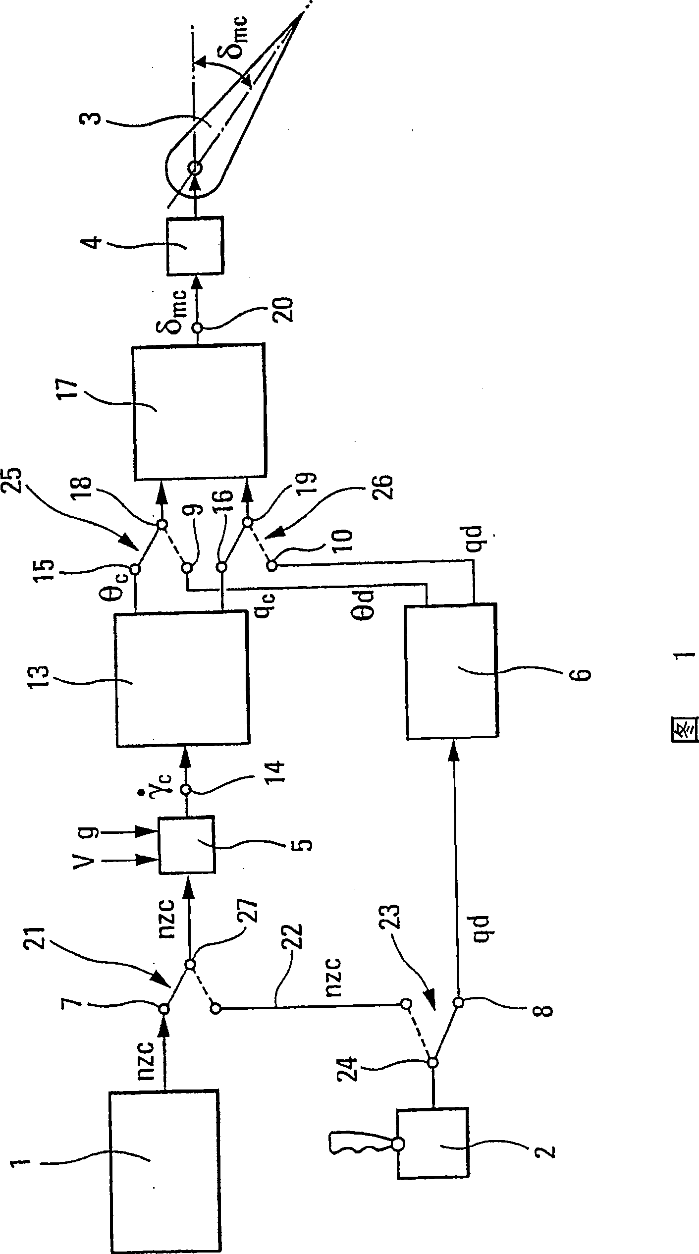
[0058] In a schematic exemplary embodiment of an aircraft flight electronic control system according to the present invention shown in FIG. 1, an autopilot 1, a joystick system 2, a direction control airfoil 3 and a device for controlling the deflection angle of the control airfoil are shown 4.

[0059] In this example, it is assumed that the autopilot 1 is capable of sending out at its output 7 an electronically controlled signal nz corresponding to the controlled value of the load factor c , while the joystick system 2 can generate or correspond to the pitch velocity desired value q at its output terminal 24 through switching action d Corresponding, or with the load factor controlled value nz c Corresponding electric control signal. Furthermore, on the one hand, a computing device 5 is provided, which is able to use the controlled value nz c An electrical signal representing the controlled value of the time derivative of aerodynamic gamma is calculated On the other hand...


PUM


Abstract

The invention relates to an electric flight control system for aircraft elevators. According to the invention, the flight control system can be controlled in terms of load factor or rate of pitch. The inventive system comprises built-in protections in relation to load factor, incidence and pitch attitude.

Description

technical field [0001] The invention relates to a flight electronic control system for controlling aircraft elevators. Background technique [0002] As we all know, in a mechanically controlled aircraft, the joystick directly controls the deflection angle of the elevator, and the magnitude of this angle is proportional to the steering amplitude of the joystick. Therefore, by operating the joystick, the pilot can exert a driving action that controls the position of the aircraft to its center of gravity or controls the attitude of the aircraft at all times. This driving action is instinctive for a pilot. [0003] It is also known that these flight electronics, which many modern aircraft are now equipped with, allow the control of the aircraft by purpose through the joystick, that is, by direct control of parameters such as the load factor, everything that happens as if the control Rods are scaled in terms of load factors. This control is advantageous because by calibrating ...

Claims


Application Information

Patent Timeline
Patent Type & Authority Patents(China)
IPC IPC(8): G05D1/06B64C13/50
CPCG05D1/0607B64C13/503
Inventor F·拉弗格尼F·威劳默
Owner AIRBUS OPERATIONS (SAS)
Why Eureka
Try Eureka