
Wave method of controlled silicon thyristor rectifier and its device

A technology of silicon thyristor and rectifier, which is applied in the field of wave generation method and device of silicon controlled thyristor rectifier, can solve the problems of reducing the output voltage quality of the rectifier, large ripple voltage of the rectifier busbar, etc., and achieves fast real-time response and accurate SCR switching. Phase operation, the effect of improving quality

Active Publication Date: 2009-06-24
EMERSON NETWORK POWER CO LTD
View PDF5 Cites 0 Cited by
  • Summary
  • Abstract
  • Description
  • Claims
  • Application Information

AI Technical Summary

Problems solved by technology

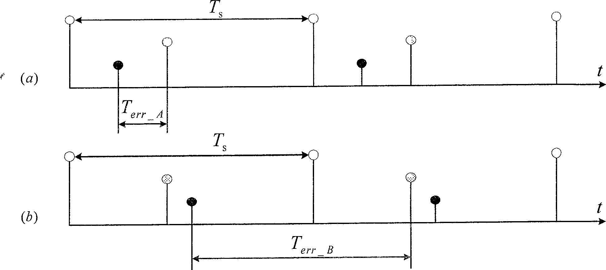
When using this method, the rectifier's wave accuracy is a T s , when T s When it is large (such as 200uS), it will cause a large ripple voltage on the bus bar of the rectifier, thereby reducing the quality of the output voltage of the rectifier

Method used


Image

  • Wave method of controlled silicon thyristor rectifier and its device
  • Wave method of controlled silicon thyristor rectifier and its device
  • Wave method of controlled silicon thyristor rectifier and its device

Examples


Embodiment Construction

[0062] The present invention is further elaborated below in conjunction with accompanying drawing and embodiment:

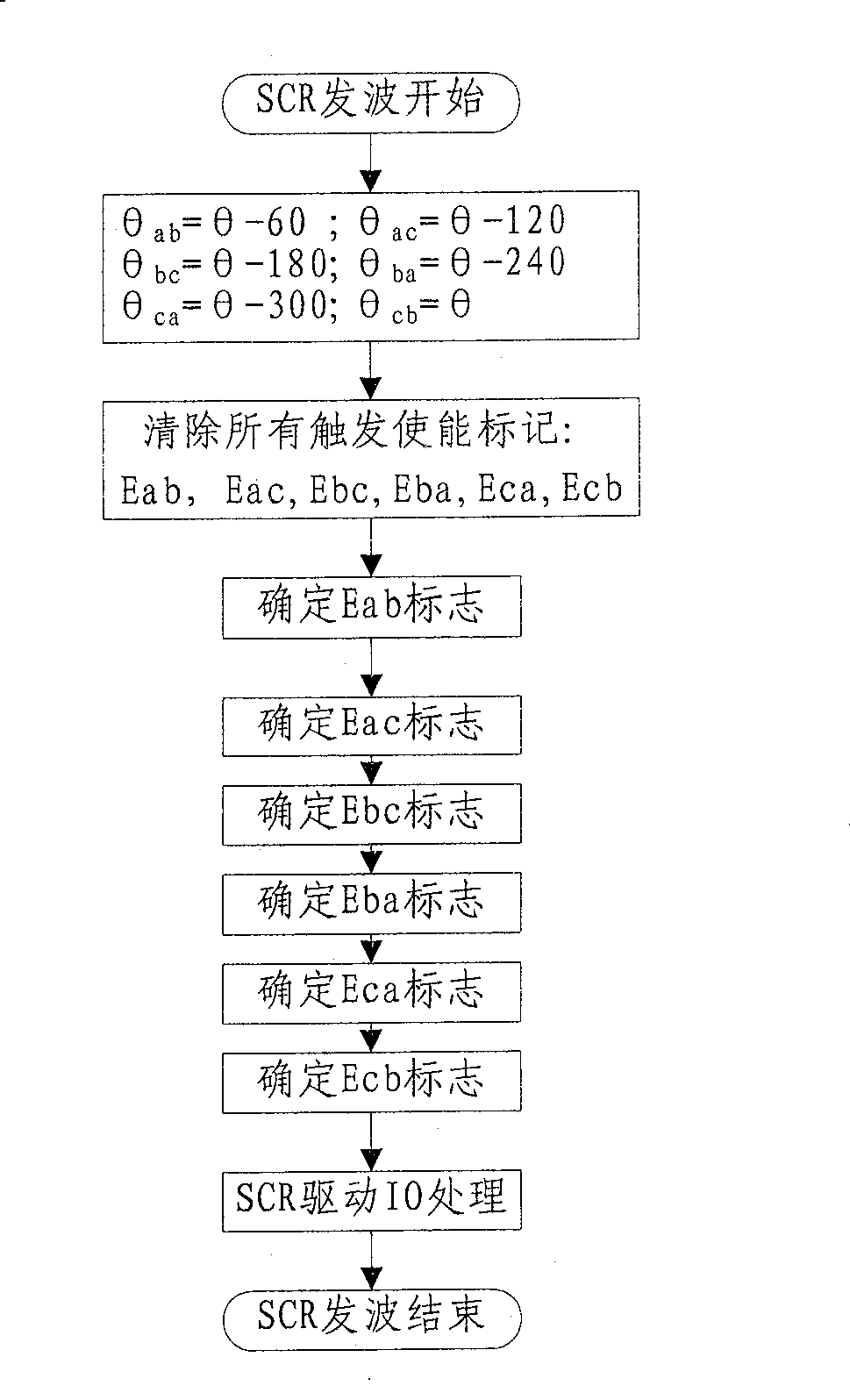
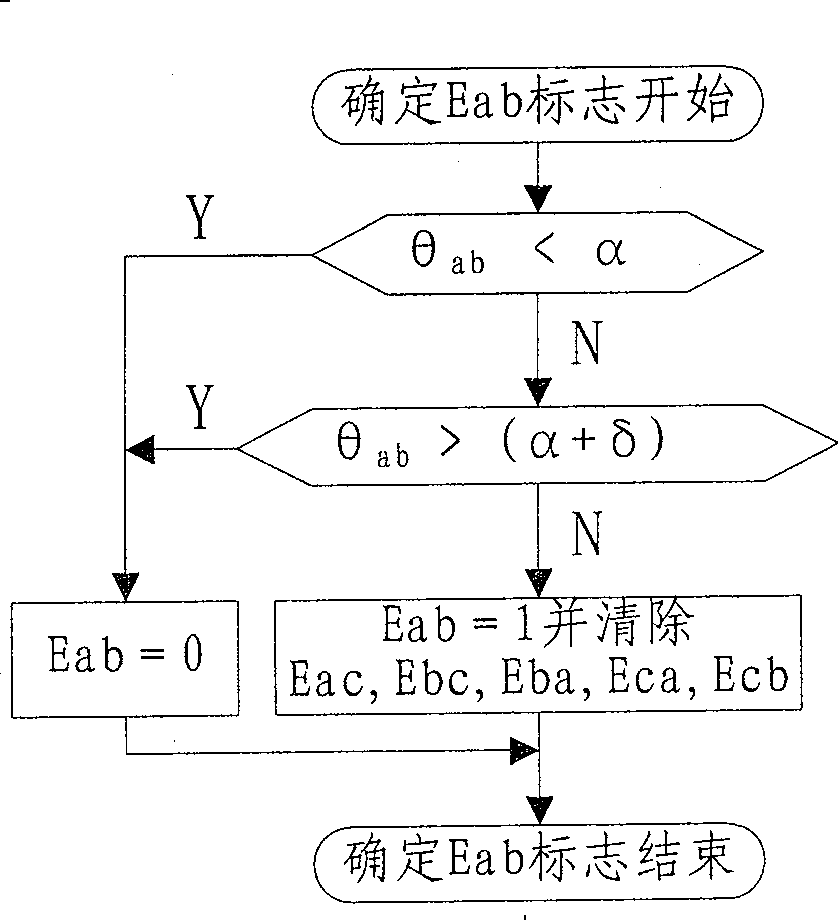
[0063] In order to solve the commutation error caused by conventional SCR wave transmission and realize accurate SCR commutation operation, the present invention adopts three methods, adding a high-priority interrupt mode in the timing interrupt, according to the phase and / or amplitude of the input voltage characteristics, as well as the firing angle of the thyristor, obtain the precise moment of commutation of each thyristor in the rectifier, and preset the precise commutation time into the comparison unit of the timer, when the commutation time matches the timer A timer comparison interrupt occurs, and the SCR commutation operation is performed in the timer comparison interrupt service subroutine to realize accurate SCR commutation operation.

[0064] The specific implementation of method one is as follows:

[0065] Rewrite the previous SCR commutation conditi...


PUM


Abstract

The invention discloses a wave-generating method and device for a silicon-controlled thyristor rectifier. The method includes: obtaining each silicon-controlled thyristor in the rectifier according to the phase and / or amplitude characteristics of the input voltage and the firing angle of the silicon-controlled thyristor. The wave-emitting time; the wave-emitting time is preset in the comparison unit of the timer, if the wave-emitting time matches the timer, a timer comparison interrupt occurs, thereby commutating the corresponding thyristor operate. The device includes a signal sending module for sending a commutation operation signal to the thyristors of the rectifier; according to the phase and / or amplitude characteristics of the input voltage, and the firing angle of the thyristors of the rectifier, each thyristor in the rectifier is obtained A module for acquiring the time when the thyristor emits waves; and a timer module for locating the time when the signal sending module sends a commutation operation signal according to the time when the thyristors emit waves. The invention can realize precise SCR commutation operation and improve the quality of the output voltage of the rectifier.

Description

[technical field] [0001] The invention relates to the technical field of rectification, in particular to a method for generating waves of a thyristor rectifier and a device thereof. [Background technique] [0002] Most of the current high-power UPS adopts analog control technology. In order to improve reliability, it is an inevitable trend to change to digital control. Limited by the voltage and current stress of power devices, high-power UPS rectifiers usually use silicon-controlled thyristor (SCR) rectification technology. However, after the high-power SCR rectifier adopts digital control technology, due to the unique sampling and control delay of the digital control itself, the rectifier wave generation accuracy is reduced, which may easily lead to asymmetrical input current of the SCR rectifier, increased bus ripple and reduced system control stability. And other issues. [0003] The digital control SCR rectifier usually adopts the software framework of the main progra...

Claims


Application Information

Patent Timeline
Patent Type & Authority Patents(China)
IPC IPC(8): H02M7/155H02M1/06H02M1/08
Inventor 季建强于相旭陈保群刘代兵
Owner EMERSON NETWORK POWER CO LTD
Learn More