Control method of multi-pulse thyristor trigger based on delay compensation

A delay compensation and control method technology, applied in the direction of output power conversion device, electrical components, AC power input conversion to DC power output, etc., to improve the accuracy of wave transmission, improve operating efficiency and reliability, and reduce resource occupation Effect

Active Publication Date: 2017-08-01
WISDRI WUHAN AUTOMATION
View PDF2 Cites 0 Cited by
  • Summary
  • Abstract
  • Description
  • Claims
  • Application Information

AI Technical Summary

Problems solved by technology

[0003] The technical problem to be solved by the present invention is to provide a multi-pulse thyristor trigger control method based on delay compensation for the defects of existing digital thyristor triggers, which can significantly improve the efficiency and reliability of system operation and maintain the DC bus voltage stability

Method used


Image

  • Control method of multi-pulse thyristor trigger based on delay compensation
  • Control method of multi-pulse thyristor trigger based on delay compensation
  • Control method of multi-pulse thyristor trigger based on delay compensation

Examples


Embodiment Construction

[0028] The present invention will be further described below in conjunction with specific examples and accompanying drawings.

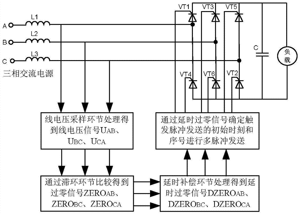
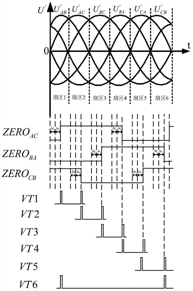
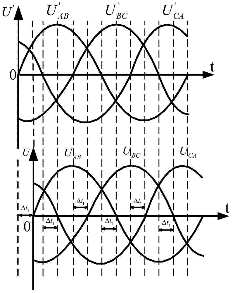
[0029] Most existing digital thyristor flip-flops are implemented in the following ways: figure 2 As shown, the AC line voltage synchronization signal corresponding to the natural commutation point is U' AC , U'BA , U' CB and is the actual three-phase AC power line voltage signal, Δt 1 is the actually measured delay time of the sampling circuit, Δt 2 The delay time is the hysteresis link filter processing, and the trigger pulse of the thyristor is a double trigger pulse signal. It can be seen from the figure that the delay time Δt 1 and Δt 2 This kind of trigger control method cannot achieve compensation. The double trigger pulse signal will cause the bus voltage to fluctuate when the load is disturbed, and the DC bus voltage will be low when the load is heavy, which will affect the operating characteristics of the load. In addition, the zero-cro...


PUM


Abstract

The invention provides a multi-pulse thyristor trigger control method based on delay compensation, which performs timing interrupt sampling with a sampling period of T for three AC line voltage signals whose phases are 60° ahead of the natural commutation point; through the hysteresis link and setting The corresponding three zero-crossing signals are obtained by comparing the hysteresis-loop zero-crossing value of the hysteresis value; the delayed zero-crossing signal whose phase is 60° ahead of the natural commutation point is obtained through the delay compensation link; the delayed zero-crossing signal is obtained according to the delayed zero-crossing signal Drive the initial time and serial number of the trigger pulse sending of 6 thyristors; from the initial moment of trigger pulse sending, according to the set number of trigger pulses N, carry out N times of trigger pulse sending processing with a period of T. Aiming at the defects of the existing digital thyristor triggers, the invention can significantly improve the efficiency and reliability of system operation, and maintain the stability of the DC bus voltage.

Description

technical field [0001] The invention belongs to the technical field of rectification, and in particular relates to a multi-pulse thyristor trigger control method based on delay compensation. Background technique [0002] Thyristor rectifiers are widely used in a variety of industrial occasions. The trigger of its core component mainly adopts analog or digital control technology. Compared with the analog trigger, the digital trigger achieves smooth start and greatly improves reliability. . At present, most digital flip-flops use the line voltage synchronous signal detection circuit to obtain 3-line voltage zero-crossing signals, obtain 3-line voltage zero-crossing signals through 3 capture units, and then obtain 6 synchronous double trigger pulse signals through 3 timer comparison units , Occupies a large number of capture interrupts and timing interrupt resources of the microprocessor (MCU), resulting in confusion and nesting of capture interrupts and timing interrupts, red...

Claims


Application Information

Patent Timeline
Patent Type & Authority Patents(China)
IPC IPC(8): H02M7/162
Inventor 王傲能余克军康现伟王国强
Owner WISDRI WUHAN AUTOMATION
Why Eureka
Try Eureka