Signal waveform deterioration compensator

a compensator and signal waveform technology, applied in the field of optical data transmission, can solve the problems of difficult one circuit to cope with such a wide variety of bit rates, poor optical fiber polarization mode dispersion, and inability to pull, so as to minimize the waveform deterioration, minimize the signal waveform deterioration automatically, and achieve the effect of compensating for a deterioration factor in optical fiber transmission

Inactive Publication Date: 2007-03-22
HITACHI LTD
View PDF26 Cites 33 Cited by
  • Summary
  • Abstract
  • Description
  • Claims
  • Application Information

AI Technical Summary

Benefits of technology

[0017] The above object can be achieved by a system in which an optical detector converts an optical digital data signal into an electric digital data signal, a sampling circuit is used to acquire an amplitude histogram by sampling the amplitude of the electric digital data signal asynchronously with a data signal bit timing, and a signal corresponding to the amount of waveform deterioration is extracted from the histogram in a control circuit, thereby obtaining a control signal which minimizes the waveform deterioration. Particularly, the amount of compensation by a variable optical signal waveform deterioration compensation circuit or a variable electric signal waveform deterioration compensation circuit can be controlled by this control signal to minimize the signal waveform deterioration automatically.
[0018] For the above signal waveform deterioration compensator, a chromatic dispersion compensation circuit, a PMD compensation circuit or a bandwidth deterioration compensation circuit or a compensation circuit which includes a transversal filter or a decision feedback equalizer is used so that compensation for a deterioration factor in optical fiber transmission can be effectively made.

Problems solved by technology

However, the above clock maximum control system has a problem that as waveform deterioration increases, the clock signal intensity loses its single-peak feature making it impossible to “pull in” for the best waveform.
The above problem exists similarly when FIG. 2 shows an automatic PMD compensator.
However, optical fiber transmission lines which have been installed include poor optical fibers whose polarization mode dispersion is large and the maximum polarization mode dispersion of such optical fibers is said to be as large as 2.0 ps / km1 / 2.
Another problem with the conventional clock extraction system is that the detection characteristics of the detection circuit largely depends on the optical signal bit rate and cannot be used for compensation for optical signals with different bit rates.
Since the clock extraction system requires the use of a bandpass filter 122 with a very narrow bandwidth (Q-value is several hundreds), it is difficult for one circuit to cope with such a wide variety of bit rates.

Method used


Image

  • Signal waveform deterioration compensator
  • Signal waveform deterioration compensator
  • Signal waveform deterioration compensator

Examples


first embodiment

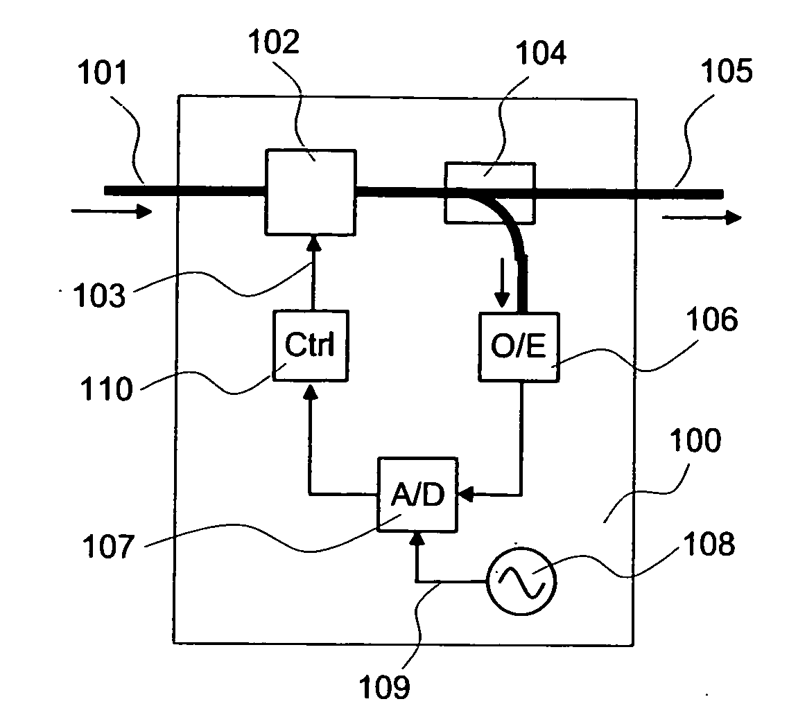
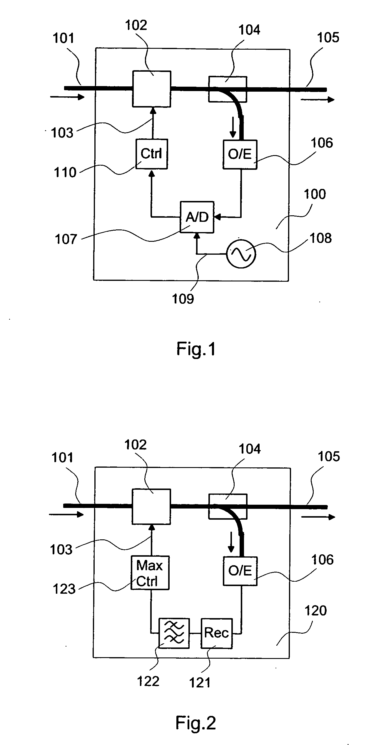
[0040]FIG. 1 is a block diagram showing the present invention and illustrates the configuration of an automatic chromatic dispersion compensator 100 according to the present invention, as an example.

[0041] An optical digital data signal entered through an input optical fiber 101 undergoes compensation for deterioration caused by chromatic dispersion as it passes through a variable optical chromatic dispersion compensator 102 and the compensated optical signal is outputted through an output optical fiber 105. Part of the compensated optical signal is branched by an optical splitter 104 and converted into an electric signal by an optical detector 106 before entering an A / D converter 107 as a sampling circuit. The A / D converter 107 samples the amplitude of the input electric signal according to the timing of a sampling clock 109 which is generated by a clock source 108 and asynchronous with the data signal. A control circuit 110 generates a chromatic dispersion control signal 103 match...

second embodiment

[0054]FIG. 7 shows the present invention and illustrates the configuration of an optical transmitter according to the present invention. An optical signal from an optical transmitter 130 is transmitted through an optical fiber transmission line 131-1, then amplified as an optical signal by an optical repeater 132 consisting of an optical amplifier like an optical fiber amplifier and transmitted again through an optical fiber transmission line 131-2, amplified by an optical preamplifier 133 and sent to an automatic chromatic dispersion compensator (or PMD compensator) 100 according to the present invention. The optical signal which has undergone waveform deterioration compensation is sent to an optical receiver 134 where it is reconverted into an electric data signal. In this arrangement, there is no communication of electric signals between the automatic chromatic dispersion compensator 100 and the optical receiver 134 and they can be completely independent from each other. This is ...

third embodiment

[0056]FIG. 8 shows the present invention and exemplifies that the present invention is applied to a wavelength division multiplexing system and incorporated in an optical receiver. Optical signals with different wavelengths λ1, λ2 and λ3 from optical transmitters 130-1, 130-2 and 130-3 are multiplexed by an optical wavelength multiplexer 137 and transmitted through a single optical fiber transmission line 131, then amplified by an optical preamplifier 133 before being demultiplexed into separate signals with wavelengths λ1, λ2 and λ3 by an optical wavelength demultiplexer 138. These different wavelength optical signals are respectively sent to automatic chromatic dispersion compensation optical receivers 135-1, 135-2 and 135-3 which incorporate automatic chromatic dispersion compensators (or PMD compensators) according to the present invention. In this configuration, an optical detector 106 is also used as an optical detecting section of an optical receiver for digital data receptio...


PUM


Abstract

The waveform deterioration detection range is broadened and multi bit rates can be handled. A chromatic dispersion compensator (or polarization mode dispersion compensator) (102) receives a waveform-deteriorated NRZ optical signal entered through an input fiber (101) and compensates it. On the other hand, an optical detector (106) receives part of output light and a sampling circuit (A/D converter) (107) performs asynchronous sampling of received waveform intensity. A control circuit (110) calculates the nth even moment (n is 4 or more) from an obtained waveform amplitude histogram and performs control to minimize its value.

Description

TECHNICAL FIELD [0001] The present invention relates to optical data transmission using optical fibers and more particularly to a compensator which compensates for deterioration of signal waveform during transmission. BACKGROUND ART [0002] In ultrahigh speed optical communications, such phenomena as chromatic dispersion, polarization mode dispersion and bandwidth limitation in transmission line optical fibers or components in use are significant limiting factors for transmission rates and transmission distances. “Chromatic Dispersion”(CD) refers to a phenomenon that light with different wavelengths travels through an optical fiber at different speeds (hereinafter what is merely called “dispersion” refers to chromatic dispersion). It is known that the optical spectrum of an optical signal modulated at a high speed contains different wavelength components and these components arrive at the receiving end at different times under the influence of chromatic dispersion, resulting in a lar...

Claims


Application Information

Patent Timeline
Patent Type & Authority Applications(United States)
IPC IPC(8): H04B10/06H04B10/2507H04B10/07H04B10/2525H04B10/2569H04B10/29H04B10/556H04J14/00H04J14/02
CPCH04B10/2507
Inventor KIKUCHI, NOBUHIKO
Owner HITACHI LTD
Why Eureka
Try Eureka