
Wavelength conversion apparatus

a technology of wavelength and conversion apparatus, which is applied in the field of wavelength conversion apparatus, can solve the problems of easy deterioration of signal waveform and upper limit of response speed, and achieve the effect of extending the transmission distance of ligh

Inactive Publication Date: 2007-07-03
SANYO ELECTRIC CO LTD +1
View PDF7 Cites 4 Cited by
  • Summary
  • Abstract
  • Description
  • Claims
  • Application Information

AI Technical Summary

Benefits of technology

The present invention provides a wavelength conversion apparatus that can make the wavelength of output light constant even when the wavelength of input light changes. This is important for use in optical network systems and other optical transmission systems. The apparatus uses two wavelength converters and filters to achieve this, and can also wavelength-convert WDM signals in multiple channels without overlapping them. The apparatus also has improved waveform quality and deterioration of signal quality is reduced.

Problems solved by technology

The inventors have studied conventional optical wavelength conversion apparatuses in detail, and as a result, have found problems as follows.
On the other hand, in Document 2, since a saturated absorption due to electric carrier is used, the upper limit of response speed is restricted, and therefore a signal waveform is easily deteriorated when a high speed TDM signal conversion is carried out.

Method used


Image

  • Wavelength conversion apparatus
  • Wavelength conversion apparatus
  • Wavelength conversion apparatus

Examples


first embodiment

of Optical Transmission System

[0111]A first embodiment of an optical transmission system according to the present invention will be then described. FIG. 19 is a diagram showing a configuration of a first embodiment of an optical transmission system according to the present invention. The optical transmission system 2 shown in FIG. 19 comprises optical transmission lines 231 to 23M, optical amplifiers 241 to 24M, and a wavelength conversion apparatus 25 between an optical transmitter 21 and an optical receiver 22. M is an integer of not less than 2. Used as the wavelength conversion apparatus 25 is the above-mentioned wavelength conversion apparatus according to the first embodiment or the second embodiment.

[0112]Light signals outputted from the optical transmitter 21 are outputted after being wavelength-converted by the wavelength conversion apparatus 25 provided just behind the optical transmitter 21. The light signals outputted from the wavelength conversion apparatus 25 are trans...

second embodiment

of Optical Transmission System

[0114]A second embodiment of an optical transmission system according to the present invention will be then described. FIG. 20 is a diagram showing a configuration of a second embodiment of an optical transmission system according to the present invention. The optical transmission system 3 shown in FIG. 20 comprises optical transmission lines 331 to 334, optical amplifiers 341 to 344, and a wavelength conversion apparatus 35 between an optical transmitter 31 and an optical receiver 32. Used as the wavelength conversion apparatus 35 is the above-mentioned wavelength conversion apparatus according to the first embodiment or the second embodiment.

[0115]Light signals outputted from the optical transmitter 31 are transmitted through the optical transmission lines 331 to 334, and are optically amplified by the optical amplifiers 341 to 344 provided halfway in the optical transmission lines, to reach the optical receiver 32. The optical receiver 23 receives th...


PUM

PropertyMeasurementUnit
lengthaaaaaaaaaa
lengthaaaaaaaaaa
lengthaaaaaaaaaa

Abstract

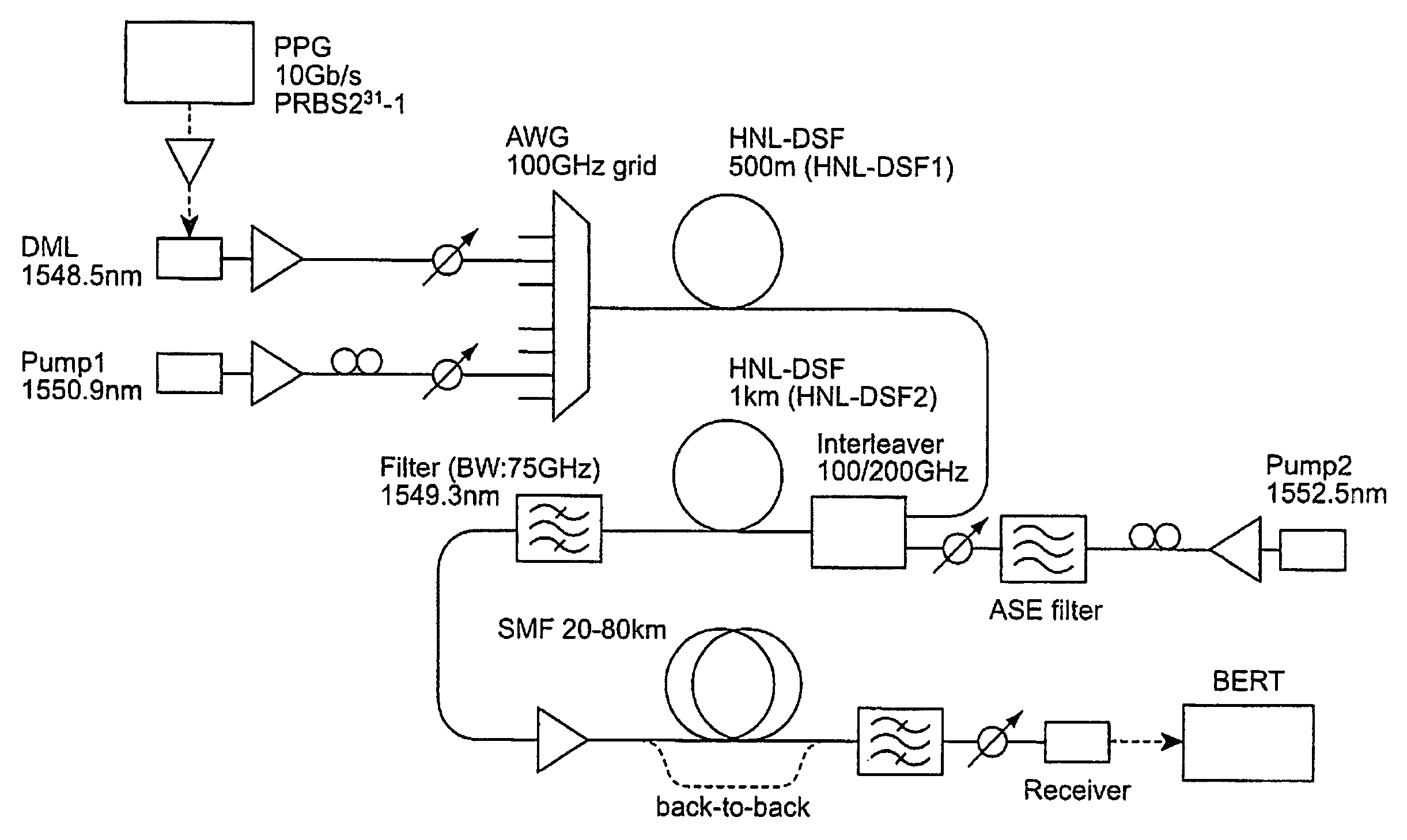
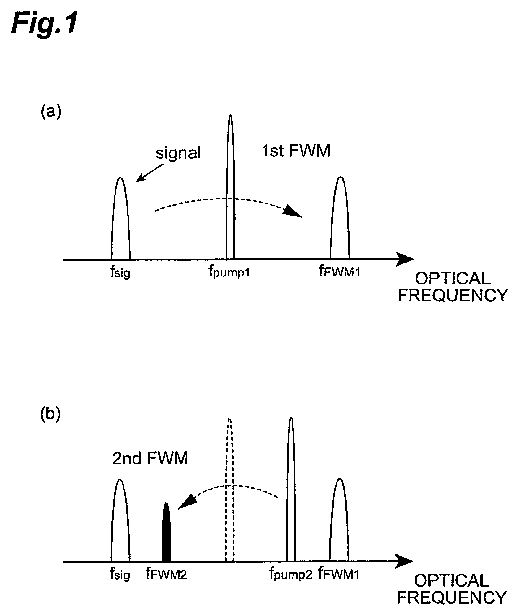
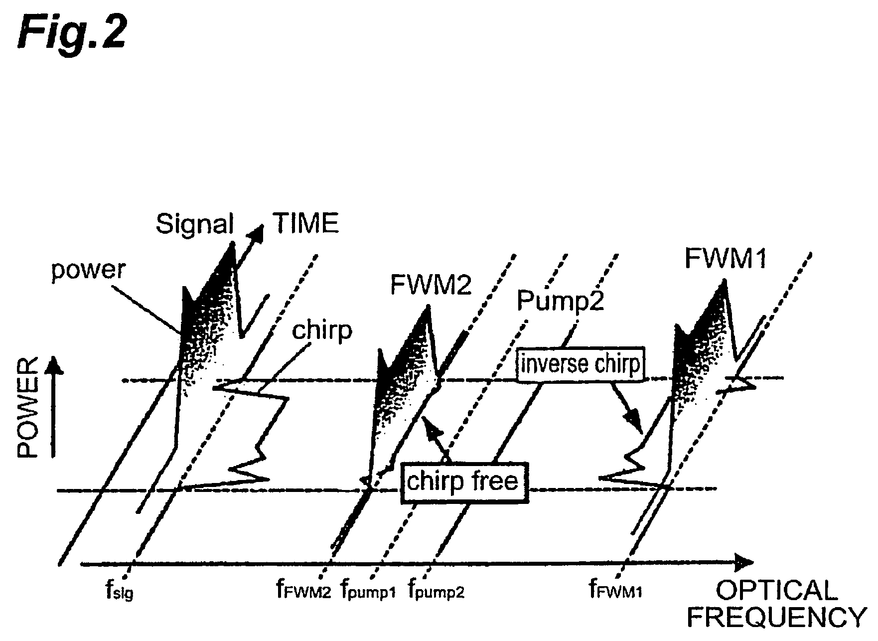
The present invention relates a wavelength conversion apparatus capable of making the wavelength of output light constant even when the wavelength of input light is changed. The wavelength conversion apparatus comprises a first wavelength converter and a second wavelength converter which are provided in series between an input terminal and an output terminal. The first wavelength converter generates four-wave mixing by input light and a first pumping light, generates an intermediate light having a new wavelength by the four-wave mixing, and outputs the intermediate light and the input light. The second wavelength converter generates four-wave mixing by the intermediate light and the input light, respectively outputted from the first wavelength converter, and a second pumping light, generates output light having a new wavelength by the four-wave mixing, and outputs the generated output light.

Description

CROSS-REFERENCE TO RELATED APPLICATION[0001]This application claims priority to Provisional Applications 60 / 570,470 and 60 / 572,115, filed on May 13, 2004 and May 19, 2004, which are hereby incorporated by reference in its entirety.BACKGROUND OF THE INVENTION[0002]1. Field of the Invention[0003]The present invention relates to a wavelength conversion apparatus for generating output light having a wavelength different from the wavelength of input light and outputting the generated output light, and an optical network system and an optical transmission system including such a wavelength conversion apparatus.[0004]2. Related Background Art[0005]A wavelength conversion apparatus can generate output light having a different wavelength (i.e., a different optical frequency) from the wavelength of input light and output the generated output light. Generally, in a wavelength conversion apparatus, the input light and pumping light are inputted to a nonlinear optical medium, to generate four-wa...

Claims


Application Information

Patent Timeline
Patent Type & Authority Patents(United States)
IPC IPC(8): G02F1/35G02F2/02H01S3/10H04J14/02
CPCG02F1/3536H04J14/0223G02F2201/16
Inventor TANAKA, MASATO
Owner SANYO ELECTRIC CO LTD
Learn More