
Amplifying optical fiber, optical fiber amplifier and optical transmission system

a technology of optical fiber and amplifier, applied in the direction of instruments, optical elements, active medium materials, etc., can solve the problems of increasing the length of the edf, deteriorating waveform, and difficulty in realizing the miniaturization of conventional l-band edfas, so as to improve the ease of accommodating optical fiber

Inactive Publication Date: 2005-08-30
SUMITOMO ELECTRIC IND LTD
View PDF11 Cites 2 Cited by
  • Summary
  • Abstract
  • Description
  • Claims
  • Application Information

AI Technical Summary

Benefits of technology

The present invention provides an optical fiber for amplification that can effectively amplify signals in the L-band, with a reduced length of the fiber and improved amplification efficiency. The optical fiber has a core region doped with Er and Al, with an Er concentration of 1,500 wt.ppm or less, an absorption loss of 10 dB / m or more but ≤25 dB / m or less, and an unsaturated absorption of 900 dB or less. The optical fiber amplifier includes the optical fiber for amplification and a pumping light source. The optical transmission system includes the optical fiber amplifier and allows high-speed, large-capacity optical transmission using signals in the L-band. The optical fiber for amplification has a reduced length of about 2 m and a polarization mode dispersion of 0.5 ps or less in the L-band. The optical fiber can be easily accommodated in the optical fiber amplifier and handling it.

Problems solved by technology

This makes it difficult to realize miniaturization of conventional L-band EDFAs.
In addition, increasing the length of the EDF will pose a problem in terms of a deterioration in waveform due to polarization mode dispersion or a nonlinear optical phenomenon.
With this increase, however, the amplification efficiency decreases due to concentration quenching.

Method used


Image

  • Amplifying optical fiber, optical fiber amplifier and optical transmission system
  • Amplifying optical fiber, optical fiber amplifier and optical transmission system
  • Amplifying optical fiber, optical fiber amplifier and optical transmission system

Examples


Embodiment Construction

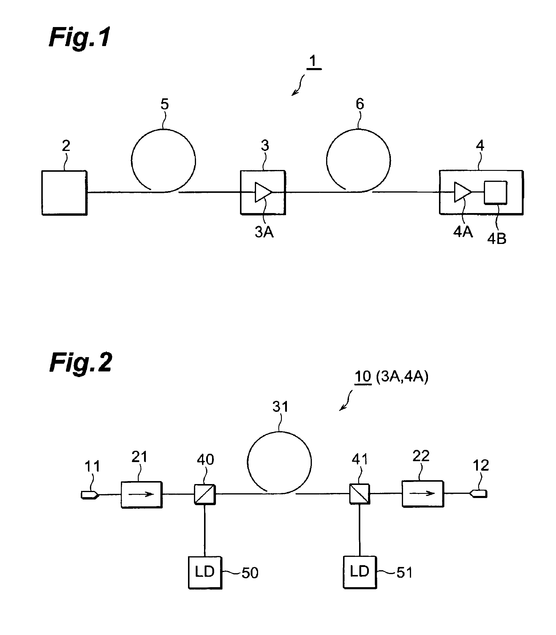
[0023]An embodiment of each of an optical fiber for amplification, optical fiber amplifier, and an optical transmission system according to the present invention will be described in detail below with reference to FIGS. 1 and 2, FIGS. 3A and 3B, and FIGS. 4 to 7. Note that the same reference numerals denote the same parts throughout the drawings, and a repetitive description will be avoided.

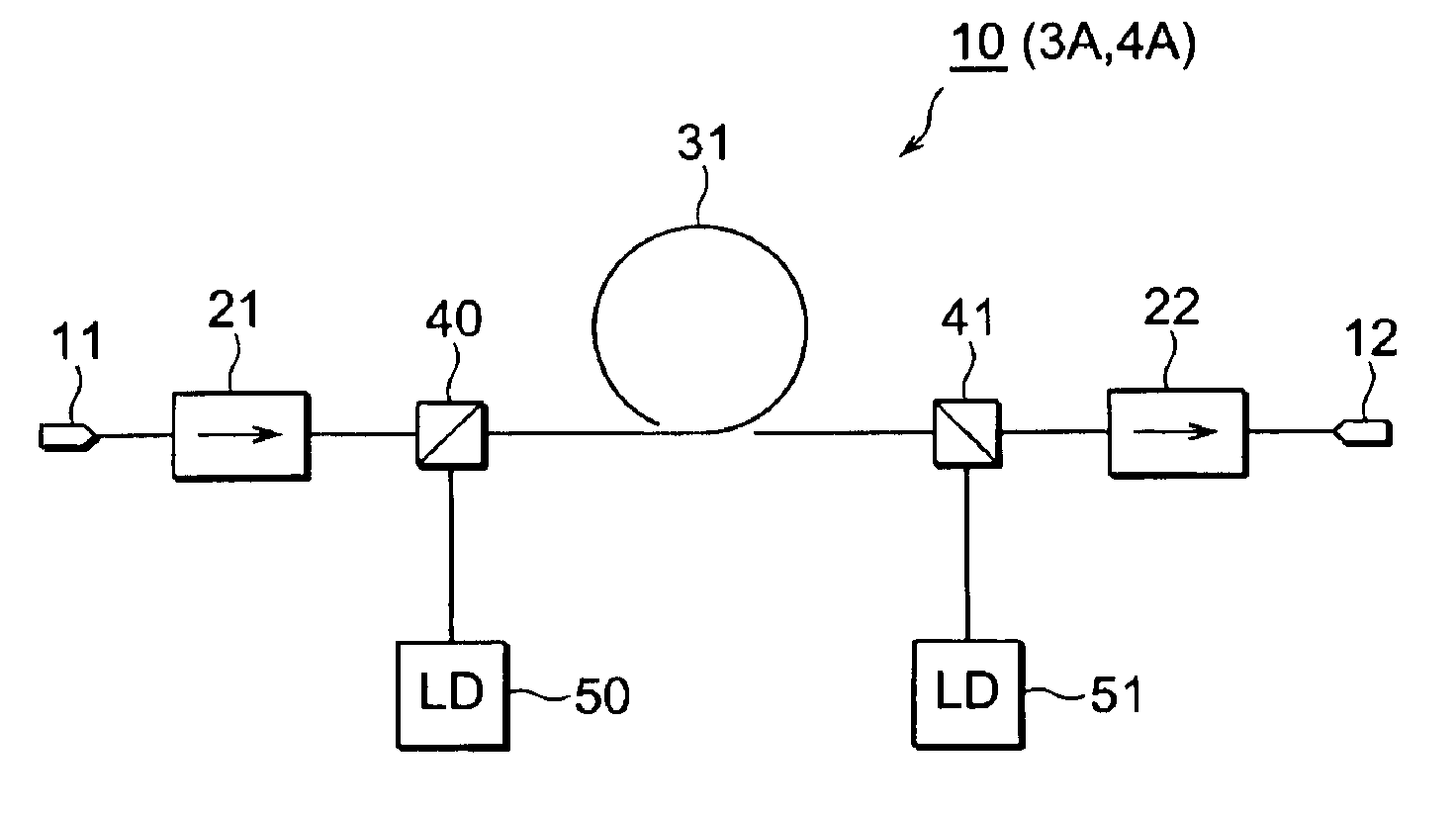
[0024]FIG. 1 is a view showing the arrangement of an embodiment of the optical transmission system according to the present invention. An optical transmission system 1 includes a transmitter 2, repeater 3, and receiver 4. The transmitter 2 and repeater 3 are connected to each other through an optical fiber transmission line 5. The repeater 3 and receiver 4 are connected to each other through an optical fiber transmission line 6. The repeater 3 incorporates an optical fiber amplifier 3A. The receiver 4 incorporates an optical fiber amplifier 4A and receiving device 4B. The optical transmission sys...


PUM


Abstract

This invention relates to an optical fiber for amplification suitable for amplifying signals in the L-band, an optical fiber amplifier including the optical fiber, and an optical transmission system. The optical fiber amplifier according to the invention includes a silica-based optical fiber as an optical fiber for amplification, which has a core region doped with Er and Al. The optical fiber for amplification has an Er concentration of 1,500 wt.ppm or less, and has the characteristics at a wavelength of 1.53 μm of: an absorption loss of 10 dB / m or more but 25 dB / m or less; and an unsaturated absorption of 900 dB or less.

Description

TECHNICAL FIELD[0001]The present invention relates to an optical fiber for amplification having a core region doped with Er, an optical fiber amplifier including the optical fiber for amplification, and an optical transmission system including the optical fiber amplifier.BACKGROUND ART[0002]An optical transmission system is designed to transmit and receive information by causing signals to propagate along an optical fiber transmission line. Since signals propagating along the optical fiber line attenuate (transmission loss), an optical fiber amplifier for amplifying signals is provided for a repeater to compensate for the loss. Conventionally, the C-band, defined as the wavelength range of 1,530 nm to 1,570 nm, is used as a signal wavelength band in the optical transmission system. As an optical fiber amplifier for amplifying signals in the respective channels in the C-band, an optical fiber amplifier (EDFA: Erbium-Doped Fiber Amplifier) having, as an amplification medium, an optica...

Claims


Application Information

Patent Timeline
Patent Type & Authority Patents(United States)
IPC IPC(8): H01S3/06H01S3/067H01S3/16
CPCH01S3/06716H01S3/1608H01S3/1693
Inventor KASHIWADA, TOMONORISUZUKI, TOSHIMI
Owner SUMITOMO ELECTRIC IND LTD
Learn More