

Optical transmitter and optical transmission system
Patent Information
- Authority / Receiving Office
- US · United States
- Current Assignee / Owner
- FUJITSU LTD
- Publication Date
- 2008-04-10
- Estimated Expiration
- Not applicable · inactive patent
Smart Images
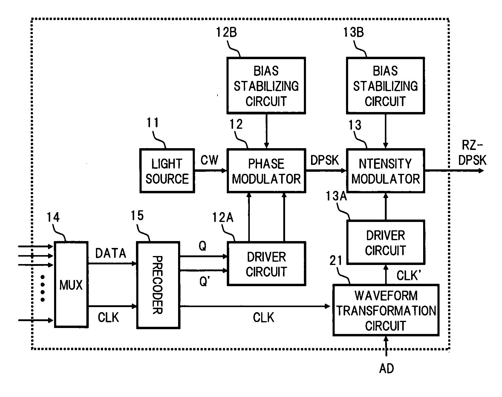
Figure 1 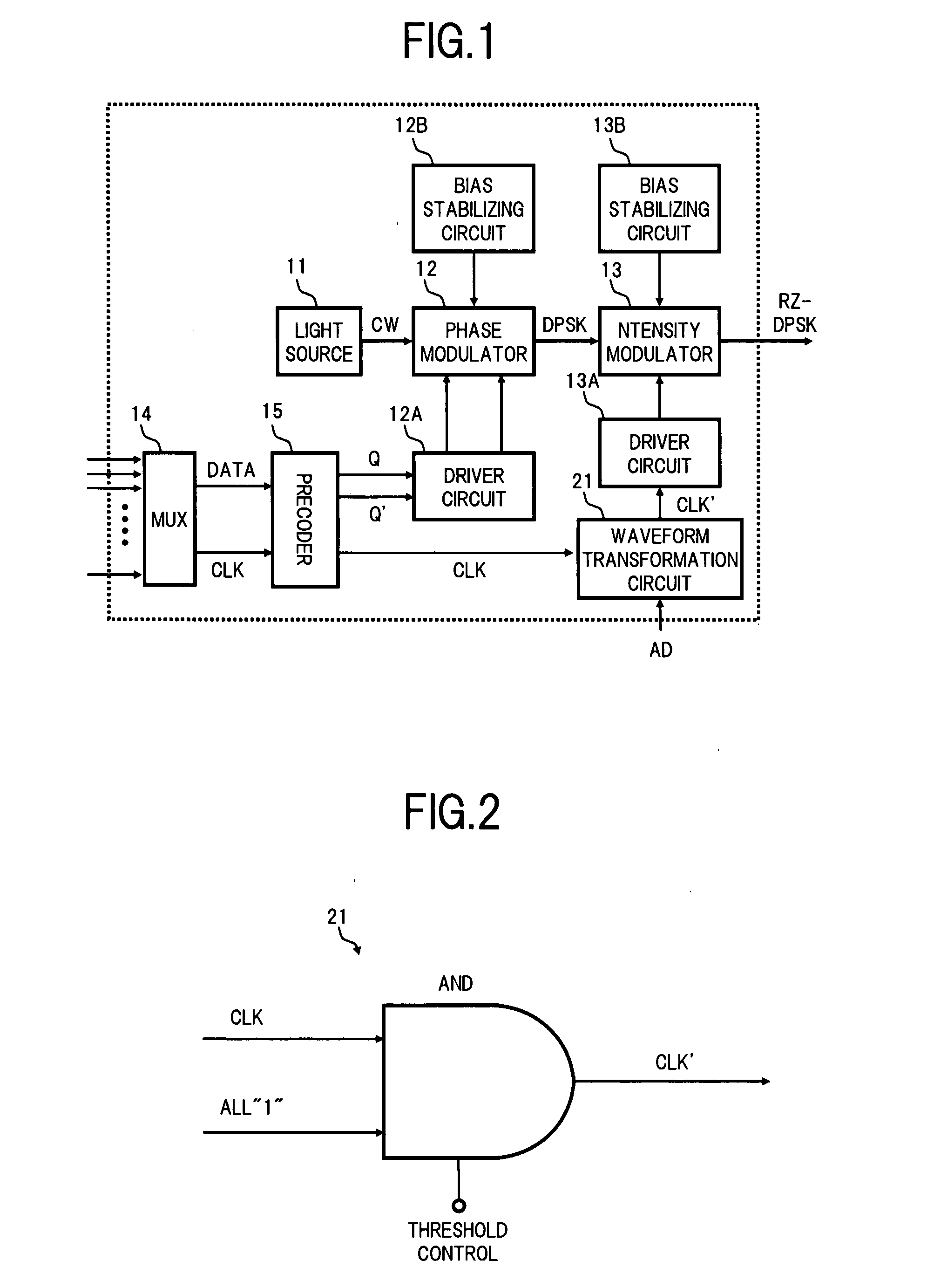
Figure 2 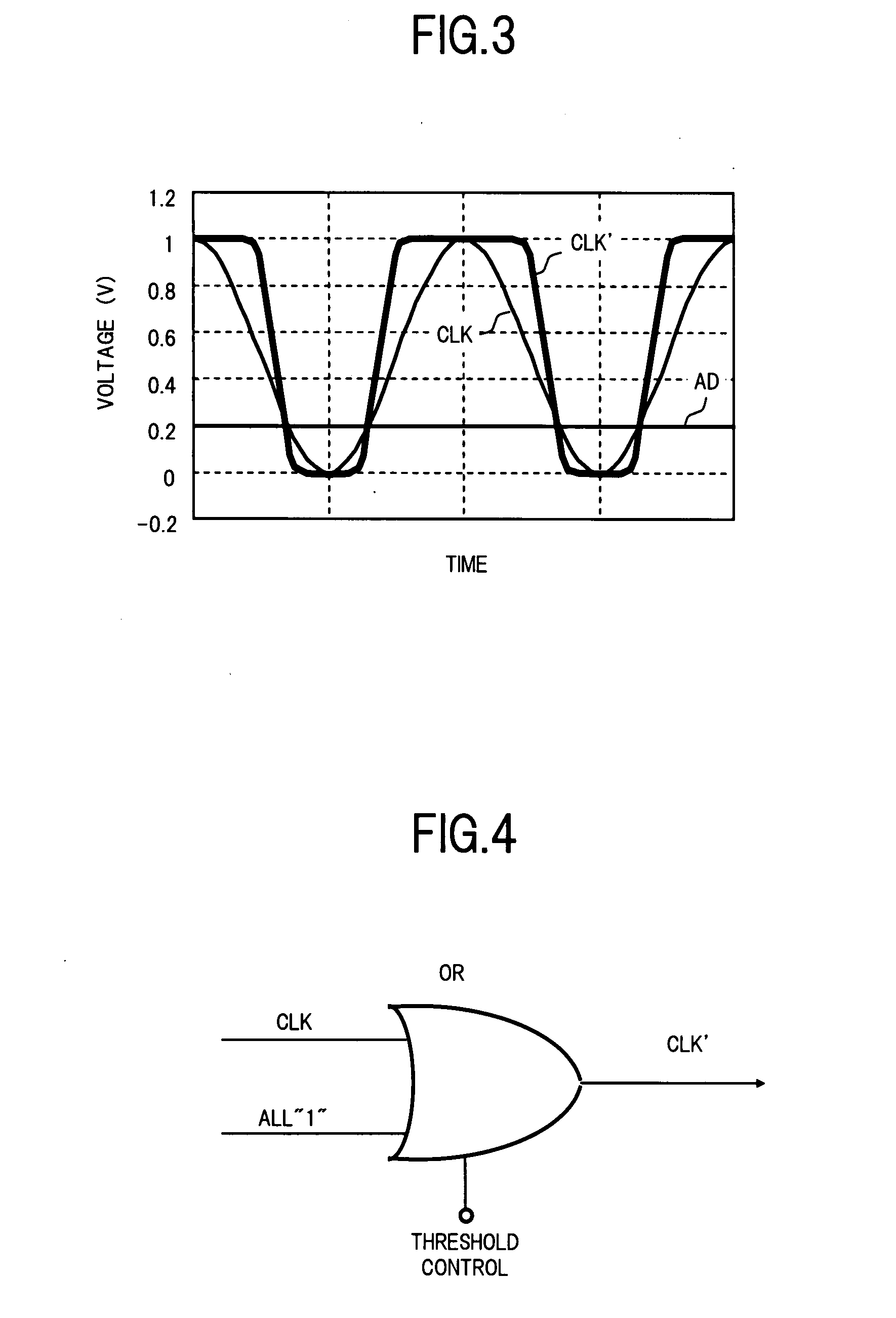
Figure 3
Abstract
Description
BACKGROUND OF THE INVENTION
[0001] 1. Field of the Invention
[0002] The present invention relates to an optical transmitter and an optical transmission system that transmit an optical signal of a phase modulation format In particular, it relates to an optical transmitter corresponding to a modulation format in which light whose phase is modulated according to data is intensity modulated in accordance with a clock to generate RZ pulses, and an optical transmission system that transmits a wavelength division multiplexed (WDM) light using a plurality of these optical transmitters.
[0003] 2. Description of the Related Art
[0004] In long distance WDM transmission, as a format for modulating the optical signal transmitted, an RZ-DPSK (Differential Phase Shift Keying) modulation format or an RZ-DQPSK (Differential Quadrature Phase Shift Keying) modulation format has superior characteristics in regards to receiver sensitivity and the like than a conventionally used RZ (Return to Zero) modul...