Heat-resistant copper foil and method for producing same, circuit board, and copper-clad laminate board and method for manufacturing same

A technology of heat resistance and copper foil, which is applied in the direction of printed circuit manufacturing, printed circuit, printed circuit, etc., to achieve excellent high-frequency characteristics, high heat-resistant adhesion, and excellent effects of copper foil

Active Publication Date: 2012-05-30
FURUKAWA ELECTRIC CO LTD
View PDF3 Cites 18 Cited by
  • Summary
  • Abstract
  • Description
  • Claims
  • Application Information

AI Technical Summary

Problems solved by technology

However, even if this material can be used as parts of recording media of mobile phones, portable electronic terminal devices, and digital devices whose application conditions are limited to daily life, it cannot maintain heat resistance due to long-term quality reliability. Adhesive under certain conditions or used in circuits with low current to 40-50A (ampere)

Method used


Image

  • Heat-resistant copper foil and method for producing same, circuit board, and copper-clad laminate board and method for manufacturing same
  • Heat-resistant copper foil and method for producing same, circuit board, and copper-clad laminate board and method for manufacturing same
  • Heat-resistant copper foil and method for producing same, circuit board, and copper-clad laminate board and method for manufacturing same

Examples


Embodiment 1

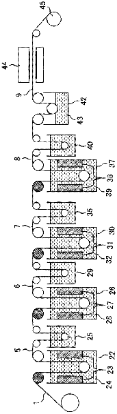
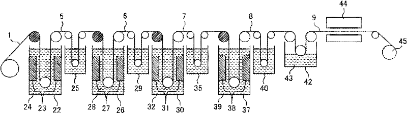
[0064] The following copper foil (electrodeposited copper foil manufactured by Furukawa Electric Co., Ltd.) was used, which was an untreated electrodeposited copper foil with a thickness of 0.035 mm produced under known electrolytic foil production conditions, and the shape of the matte surface side (plating liquid surface side) was rough. The thickness is 1.8 μm in terms of the Rz value specified in JIS-B-0601, and its elongation at normal temperature is 6.2%. On the matte side, surface treatment is applied under the following conditions.

[0065] [Primary Copper Roughening Particle Formation Bath Composition and Treatment Conditions]

[0066] Use copper sulfate, calculated as metallic copper 23.5g / l

[0067] Sulfuric acid·····100g / l

[0068] Use sodium molybdate, calculated as molybdenum 0.25g / l

[0069] Hydrochloric acid, calculated as chloride ion 0.002g / l

[0070] Ferrous sulfate, calculated as metallic iron... 0.20g / l

[0071] Chromium sulfate, calculated as trivalen...

Embodiment 2

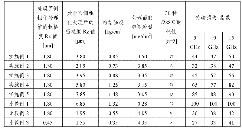
[0098] Using the untreated copper foil used in Example 1, the same roughening and surface treatment as in Example 1 were performed so that the roughness of the obtained surface treatment side was about 2.0 μm in terms of Rz value, and the same as in Example 1 was performed. Evaluation assay. The results are shown in Table 1.

Embodiment 3

[0100] Using the untreated copper foil used in Example 1, the same roughening and surface treatment as in Example 1 were performed so that the roughness of the obtained surface treatment side was about 4.0 μm in terms of Rz value, and the same as in Example 1 was performed. Evaluation assay. The results are shown in Table 1.


PUM

PropertyMeasurementUnit
Adhesion amountaaaaaaaaaa
thicknessaaaaaaaaaa
surface roughnessaaaaaaaaaa

Abstract

Disclosed is a copper foil which has excellent high frequency characteristics and heat resistance, while achieving high heat-resistant adhesion to a resin substrate at the same time. Specifically disclosed is a heat-resistant copper foil which has a configuration wherein a primary roughened surface layer which has been subjected to a primary roughening process by copper metal, a secondary roughened surface layer which has been subjected to a secondary roughening process by copper metal, and a tertiary processed surface layer which has been subjected to a tertiary processing process by zinc metal are sequentially provided on one surface of an unprocessed copper foil. Also specifically disclosed are: a circuit board which is obtained by laminating the heat-resistant copper foil on a flexible resin substrate or a rigid resin substrate; and a method for manufacturing a copper-clad laminate board wherein the heat-resistant copper foil and a heat-resistant resin substrate are thermally pressure-bonded and the tertiary processed surface layer, which is composed of the roughened copper metal and the zinc metal, is alloyed.

Description

technical field [0001] The present invention relates to a heat-resistant copper foil that can withstand high temperature and high humidity conditions and has excellent high-frequency transmission that is indispensable in communication terminal functions and a method for preparing the heat-resistant copper foil characteristic. [0002] In addition, the present invention also relates to an electronic circuit board for automobile control, which can withstand high temperature and high humidity conditions of hybrid electric vehicles, electric vehicles (hereafter referred to as HEV vehicles, EV vehicles), etc., which require long-term reliability in particular, and has Excellent high-frequency transmission characteristics indispensable for communication terminal functions. [0003] In addition, the present invention also relates to a copper-clad laminate obtained by laminating the heat-resistant copper foil and a heat-resistant resin substrate, and a preparation method thereof. B...

Claims


Application Information

Patent Timeline
Patent Type & Authority Applications(China)
IPC IPC(8): C25D7/06B32B15/08H05K1/09H05K3/00
CPCC25D3/32C25D3/38H05K1/0242C25D1/04H05K2201/0355H05K2203/0723B32B15/20C25D5/16C25D7/0614H05K3/384C25D11/38B32B15/08C25D5/48C23C18/122C25D5/10H05K2203/0307C23C18/16C25D5/605C25D5/611Y10T428/12535Y10T428/12549Y10T428/12792C25D7/06H05K1/09H05K3/00
Inventor 小黑了一星野和弘
Owner FURUKAWA ELECTRIC CO LTD
Why Eureka
Try Eureka