
Reception device, receiving method, communication system, and communication method

Inactive Publication Date: 2012-03-15
SHARP KK
View PDF2 Cites 19 Cited by
  • Summary
  • Abstract
  • Description
  • Claims
  • Application Information

AI Technical Summary

Benefits of technology

[0022]According to the present invention, the inter-symbol interference and the inter-carrier interference can be cancelled without increasing overhead, such as control signals, thereby improving the transmission characteristics.

Problems solved by technology

Regarding the OFDM, if there is a delayed wave exceeding a guard interval length, however, a previous symbol is included in an FFT (Fast Fourier Transform) section, thereby causing inter-symbol interference (ISI).
Additionally, a boundary between two adjacent symbols, that is, a discontinuous section of a signal is included in the FFT section, thereby causing inter-carrier interference (ICI).
Thus, the inter-symbol interference and the inter-carrier interference cause deterioration of characteristics.
In the case of the OFDMA, if a delayed wave exceeding the guard interval length is present, the inter-symbol interference and the inter-carrier interference occur, thereby causing deterioration of transmission characteristics for each user.

Method used


Image

  • Reception device, receiving method, communication system, and communication method
  • Reception device, receiving method, communication system, and communication method
  • Reception device, receiving method, communication system, and communication method

Examples


first embodiment

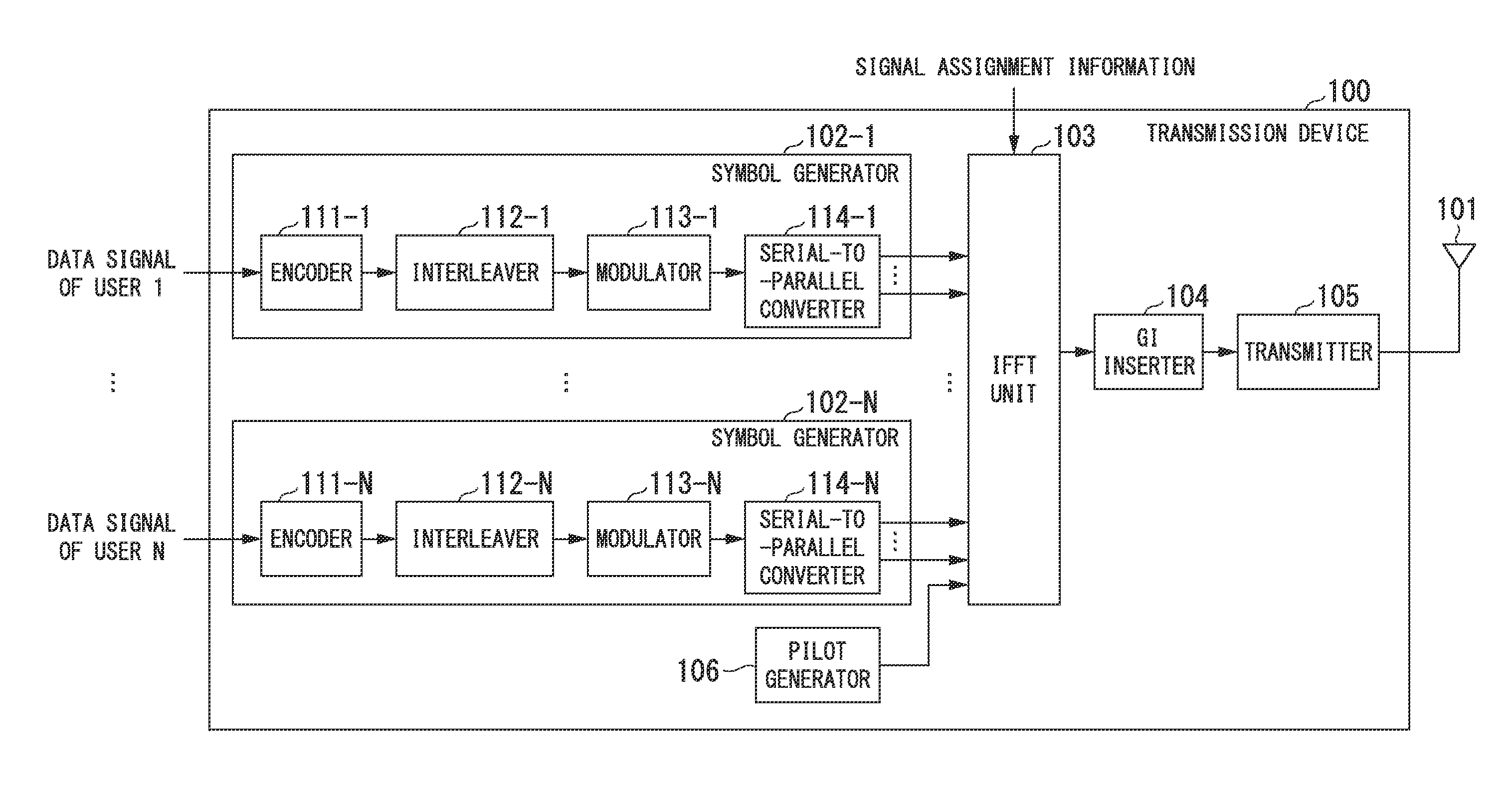
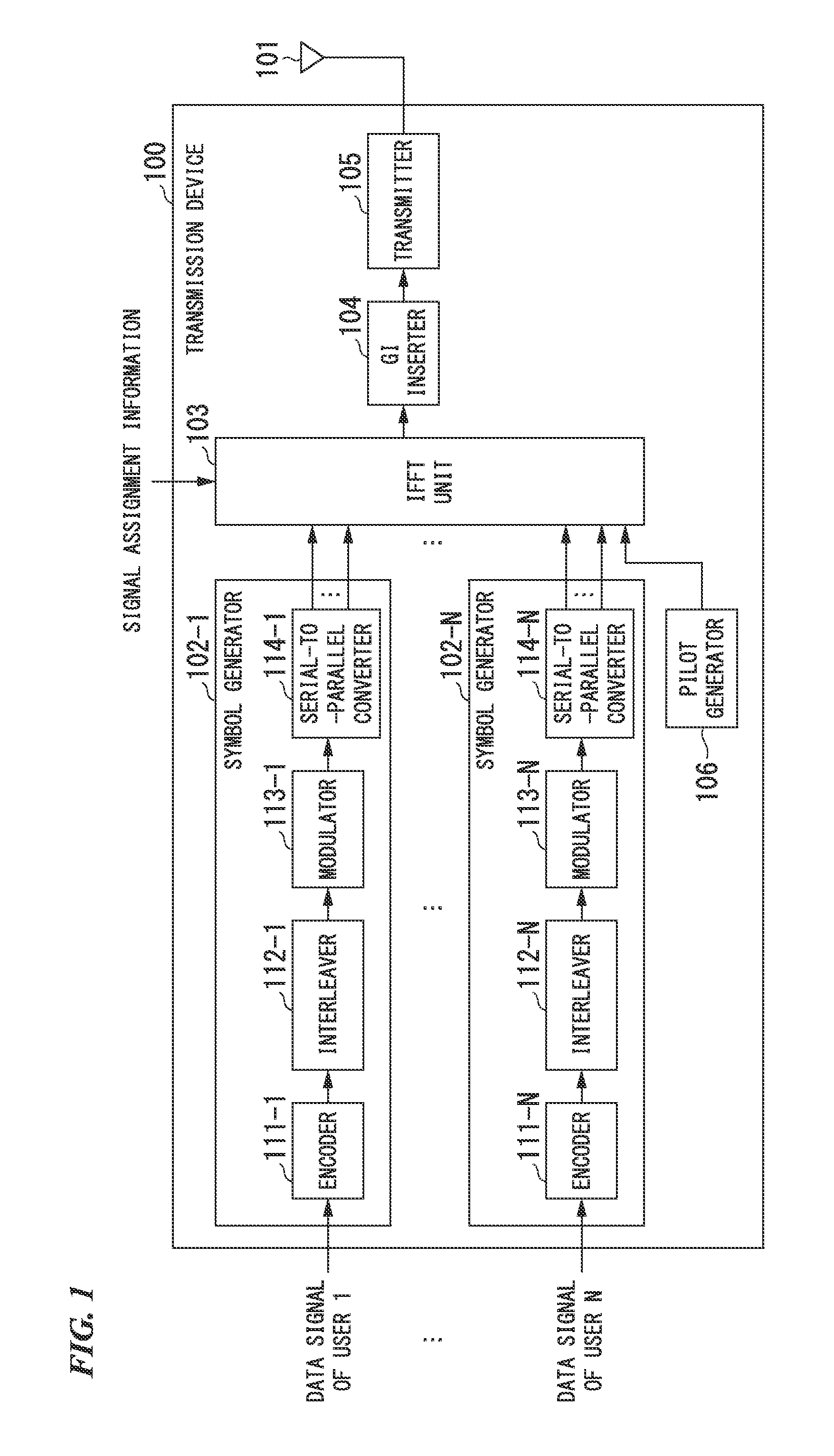
[0039]A communication system according to a first embodiment of the present invention includes: a transmission device 100 configured to transmit an OFDMA signal in which multiple users are assigned to OFDM subcarriers; and a reception device 200 configured to receive the signal transmitted from the transmission device 100. For example, the transmission device 100 is installed in a base station for downlink of a mobile communication system. The reception device is installed in a mobile terminal for downlink of the mobile communication system. Hereinafter, explanations are given with a case in which the transmission device 100 is installed in a base station in a cellular system, and the reception device 200 is installed in one of multiple mobile terminals linked to the base station.

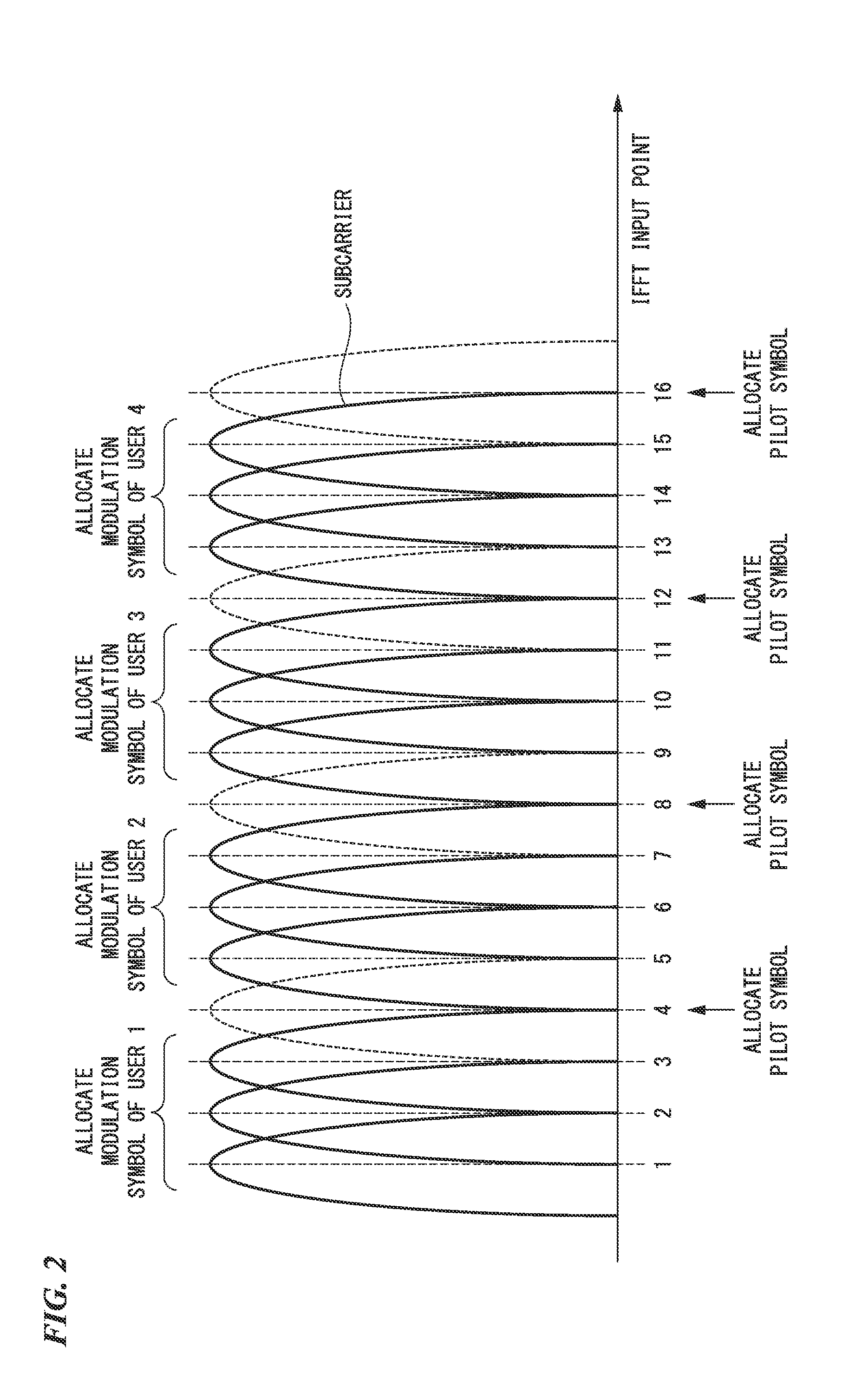
[0040]FIG. 1 is a schematic block diagram illustrating a configuration of the transmission device 100 according to the first embodiment of the present invention. The transmission device 100 includes: symbol...

second embodiment

[0088]A communication system according to a second embodiment of the present invention includes: a transmission device 300 configured to transmit an OFDMA signal, in which multiple users are assigned to OFDM subcarriers; and a reception device 400 configured to receive the signal transmitted from the transmission device 300. Hereinafter, the transmission device 300 is installed in a base station included in a cellular system. The reception device 400 is installed in one of multiple mobile terminals linked to the base station.

[0089]FIG. 8 is a schematic block diagram illustrating a configuration of the transmission device 300 according to the second embodiment of the present invention. The transmission device 300 includes: the symbol generators 102-1 to 102-N; an IFFT unit 303; the GI inserter 104; the transmitter 105; the pilot generator 106; and the control signal generator 306. The antenna unit 101 is connected to the transmitter 105. N denotes the number of users who can be linke...


PUM


Abstract

The filtering unit (203) is configured to perform a filtering process in a time domain so as to reduce a signal element of a non-desired user from a received signal. The interference canceller (205) is configured to cancel, from the signal having been subjected to the filtering process, an interference element generated using a result of a decoding process performed on the signal having been subjected to the filtering process, and outputs a result thereof. A signal detector (209) is configured to perform a decoding process on the signal output from the interference canceller and to output a result of the decoding process.

Description

TECHNICAL FIELD[0001]The present invention relates to a reception device, a receiving method, a communication system, and a communication method.[0002]Priority is claimed on Japanese Patent Application No. 2009-128748, filed May 28, 2009, the content of which is incorporated herein by reference.BACKGROUND ART[0003]Regarding a wireless communication system, for example, a transmission method using OFDM (Orthogonal Frequency Division Multiplexing) enables, by multi-carrier conversion and insertion of a guard interval, a reduction in effects of multi-path fading caused by high-speed digital signal transmission. Regarding the OFDM, if there is a delayed wave exceeding a guard interval length, however, a previous symbol is included in an FFT (Fast Fourier Transform) section, thereby causing inter-symbol interference (ISI). Additionally, a boundary between two adjacent symbols, that is, a discontinuous section of a signal is included in the FFT section, thereby causing inter-carrier inter...

Claims


Application Information

Patent Timeline
IPC IPC(8): H04B1/10H04B15/00
CPCH04J11/004H04L25/0204H04L25/03012H04L2025/0342H04L27/2647H04L2025/03401H04L2025/03414H04L25/03171
Inventor YOSHIMOTO, TAKASHIYAMADA, RYOTAKATO, KATSUYA
Owner SHARP KK
Learn More