Multi-beam antenna transmitter/receiver and transmitting/receiving method and transmission beam selection method

Inactive Publication Date: 2005-07-14
NEC CORP
View PDF8 Cites 19 Cited by
  • Summary
  • Abstract
  • Description
  • Claims
  • Application Information

AI Technical Summary

Benefits of technology

[0035] It is an object of the present invention to provide a multi-beam antenna transmitter/receiver, transmitting/receiving method, and transmission beam selec

Problems solved by technology

A problem of the conventional multi-beam antenna transmitter/receiver as shown in FIG. 7 is deterioration of the transmission characteristic.
The conventional multi-beam antenna transmitter/r

Method used


Image

  • Multi-beam antenna transmitter/receiver and transmitting/receiving method and transmission beam selection method
  • Multi-beam antenna transmitter/receiver and transmitting/receiving method and transmission beam selection method
  • Multi-beam antenna transmitter/receiver and transmitting/receiving method and transmission beam selection method

Examples


Embodiment Construction

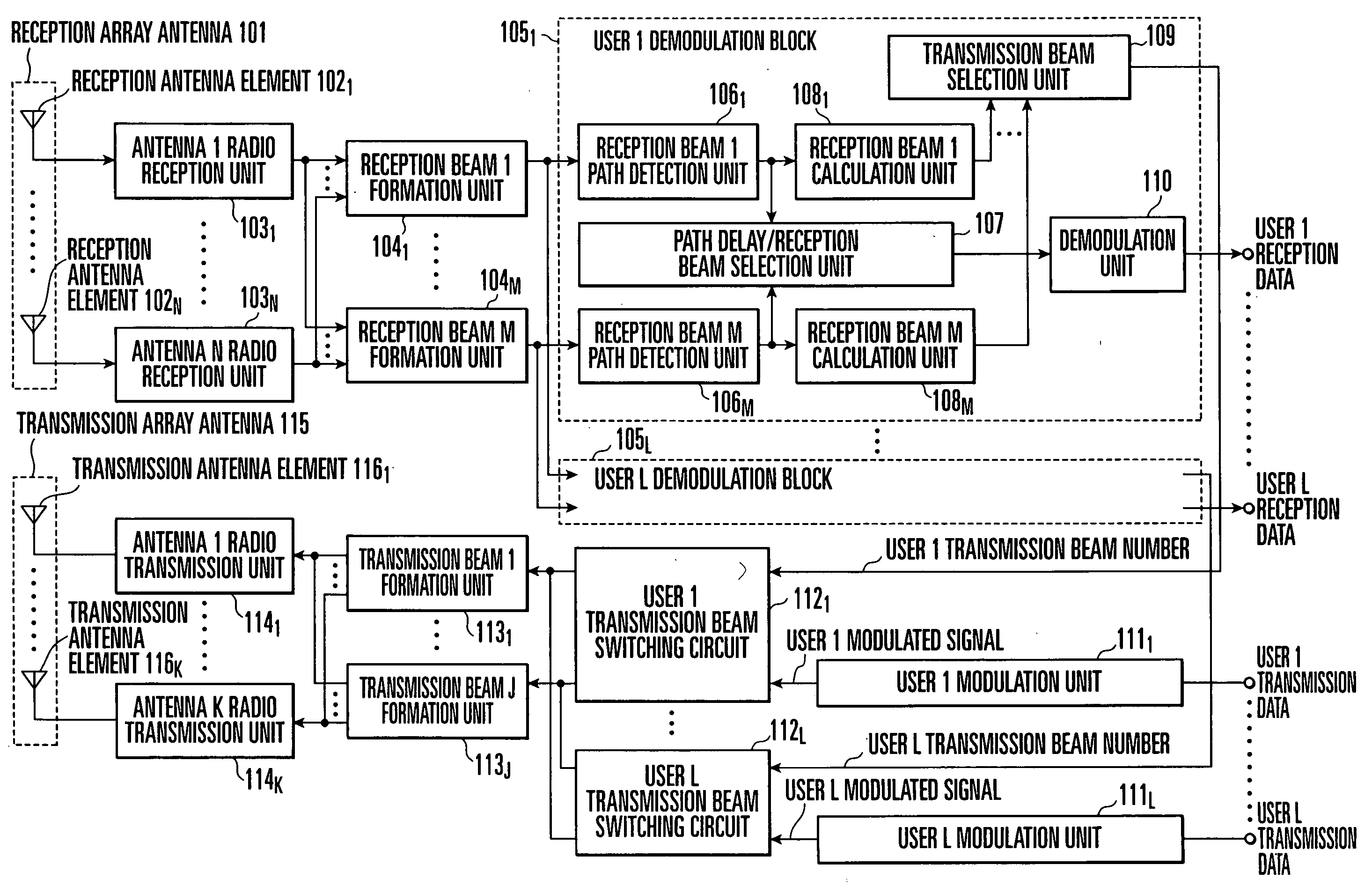
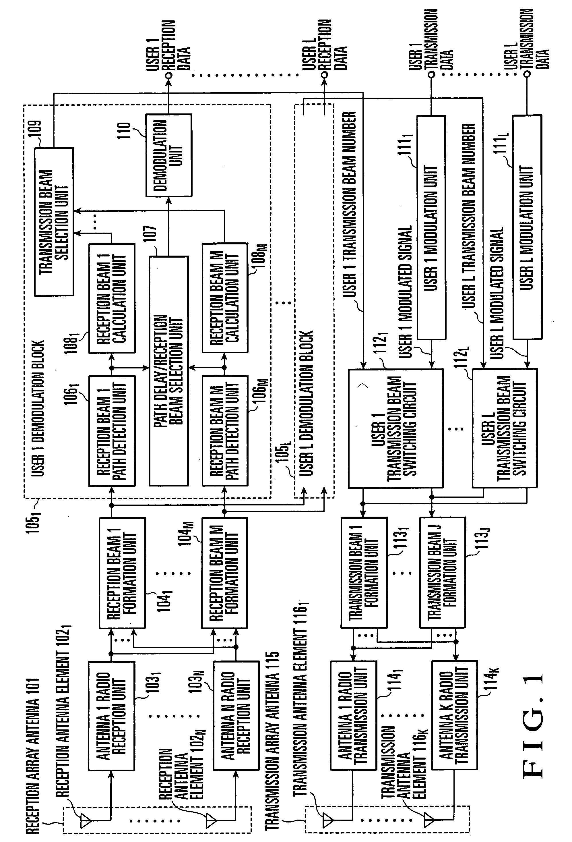
[0070] An embodiment of the present invention will be described in detail with reference to the accompanying drawings. In the following description, the number of users is L (L is an integer of 1 or more), the number of reception antenna elements is N (N is an integer of 1 or more), the number of reception beams is M (M is an integer of 1 or more), the number of transmission beams is J (J is an integer of 1 or more), and the number of transmission antenna elements is K (K is an integer of 1 or more). Hence, users are user 1 to user L, and L user signals are a user 1 signal to user L signal. Reception beams are reception beam 1 to reception beam M, and transmission beams are transmission beam 1 to transmission beam J. A multi-beam antenna transmitter / receiver having these settings will be explained.

[0071] Referring to FIG. 1, the multi-beam antenna transmitter / receiver according to the present invention comprises a reception array antenna 101, reception antenna elements 1021 to 102N...


PUM


Abstract

A multi-beam antenna transmitter/receiver includes reception beam formation units (1041-104M) which form a plurality of reception beams, and transmission beam formation units (1131-113J) which form a plurality of transmission beams. The multi-beam antenna transmitter/receiver further includes reception beam calculation units (1081-108M) which calculate overall reception qualities from the reception qualities for the path delays of user signals for respective reception beams, and a transmission beam selection unit (109) which selects a reception beam excellent in overall reception quality and selects a transmission beam having a direction which coincides with or is close to the direction of the selected reception beam. An optimum transmission beam can be selected even in the multipath environment.

Description

BACKGROUND OF THE INVENTION [0001] The present invention relates to an array antenna transmitter / receiver which suppresses interference with another user by control of antenna directivity and, more particularly, to a multi-beam antenna transmitter / receiver, transmitting / receiving method, and transmission beam selection method which select transmission / reception directivity from a plurality of fixed directional patterns (multi beams). [0002] In a cellular mobile communication system and the like, it has been examined to apply a method of forming a directional pattern (beam) which increases the transmission / reception gain in a desired signal direction and decreases it in another direction by using an array antenna transmitter / receiver including a plurality of antenna elements for the purpose of a higher-speed, higher-quality signal and a larger subscriber capacity. One of such methods is a multi-beam method of selecting a transmission / reception beam from a plurality of fixed direction...

Claims


Application Information

Patent Timeline
IPC IPC(8): H01Q3/26H01Q25/00H04B7/04H04B7/06H04B7/08H04J99/00
CPCH01Q3/26H04B7/0408H04B7/0608H04B7/0897H04B7/082H04B7/088H04B7/0617
Inventor MARUTA, YASUSHI
Owner NEC CORP
Why Eureka
Try Eureka