
Surgical appliance for milling acetabulum

A surgical operation and instrument technology, applied in the field of surgical instruments for milling acetabulum, can solve the problems of difficulty and increase in applying axial machining force, etc.

Inactive Publication Date: 2009-07-08
WALDEMAR LINK GMBH & CO
View PDF5 Cites 0 Cited by
  • Summary
  • Abstract
  • Description
  • Claims
  • Application Information

AI Technical Summary

Problems solved by technology

This increases the difficulty of precisely aligning the milling tool with the glenoid axis and applying axial machining forces

Method used


Image

  • Surgical appliance for milling acetabulum
  • Surgical appliance for milling acetabulum
  • Surgical appliance for milling acetabulum

Examples


Embodiment Construction

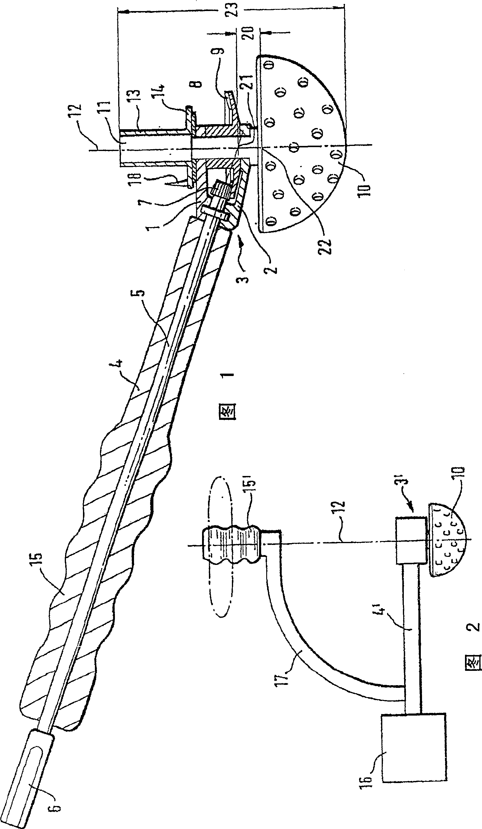
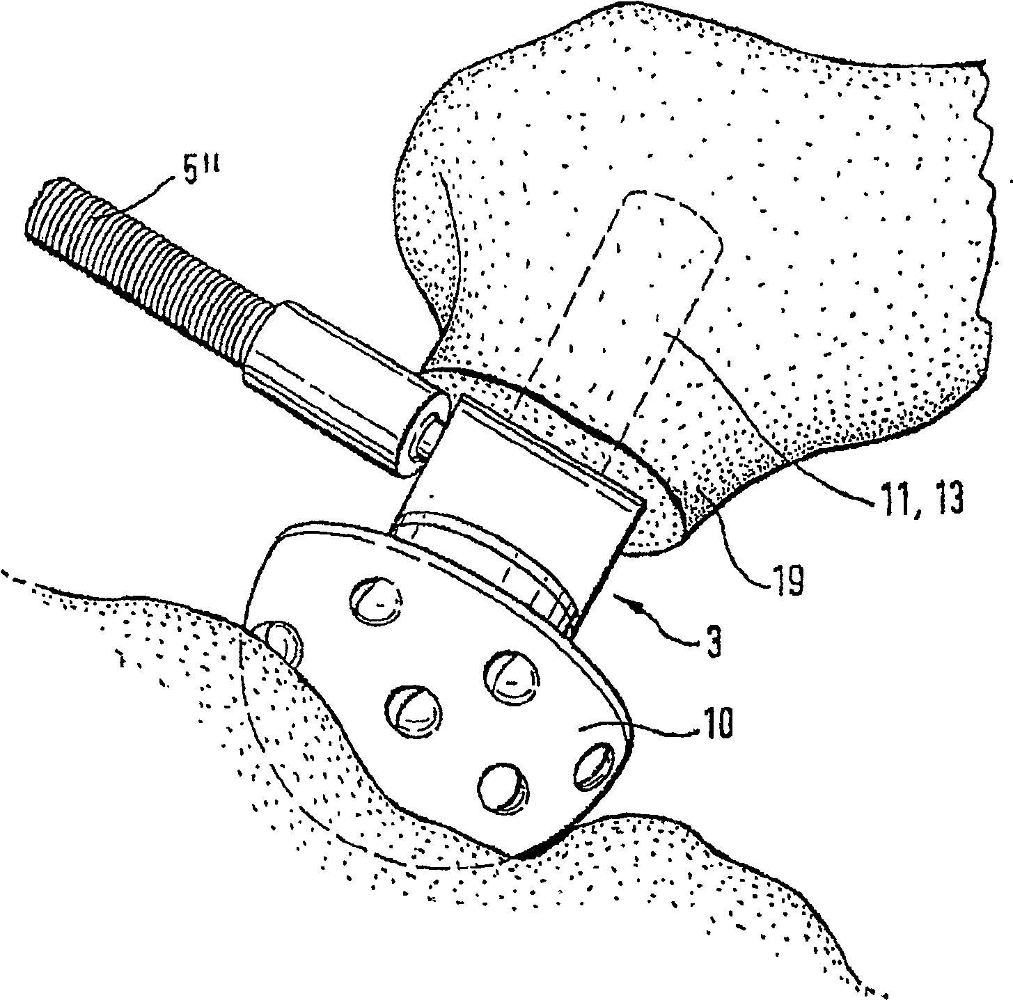
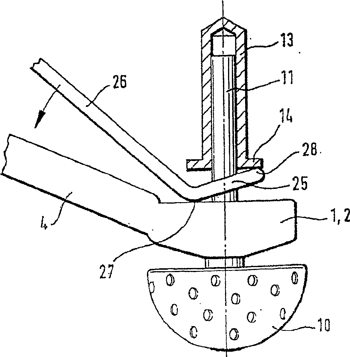
[0018] The housing parts 1, 2 of the instrument head 3 shown in Fig. 1 are firmly connected to a rod 4, which constitutes a handle 15 and includes a drive shaft 5, the free end 6 of which can be connected to a drive motor or manually in a known manner. The drive is connected with a handle. Inside the housing 1 , 2 a drive pinion 7 is mounted on the drive shaft 5 .

[0019] A milling cutter shaft 8 is mounted rotatably transverse to the drive shaft 5 in the housing 1 , 2 of the instrument head 3 . The angle between the milling cutter shaft and the drive shaft is suitably 90°-135° (110° in the example shown). A bevel gear 9 is mounted on the milling cutter shaft, the teeth of which mesh with the teeth of the driving pinion 7. In this way, the milling cutter shaft 8 can be driven in rotation by the drive shaft 5 . Of course, this is only one example of a drive connection between the two shafts. Other transmission forms can also be used, for example, a worm gear transmission. ...


PUM


Abstract

The surgical instrument used for milling the acetabulum includes an instrument head (3) and a drive shaft (5). In order to enable easy access during minimally invasive surgical procedures, the drive shaft (5), including an optional rod (4), is inclined relative to the axis of rotation (12) of the instrument head (3). In order to simplify the directional alignment of the instrument head (3) and the application of the feed force, a handle can be provided which is located in the direction of the axis of rotation (12) of the instrument head (3) but outside of this axis of rotation (12) and connected to the instrument. Head (3) or rod (4) connection.

Description

technical field [0001] The present invention relates to a surgical instrument, especially a surgical instrument for milling acetabulum. Background technique [0002] In order to fit the acetabular component into the natural socket, the socket must be milled. To this end, it has hitherto been necessary to be able to freely approach the glenoid socket axis in order to be able to attach a milling tool with a shank extending along the milling cutter axis. The tool is suitable for minimally invasive surgical procedures if a corresponding hole is machined through the proximal femur (WO 01 / 91648, US-A-2785673). This complicates and weakens the femur. For poor accessibility, milling tools are known (US-A-5176711, US-A-4808185, US-B-6364910 unpublished) in which the drive shaft is inclined relative to the axis of rotation of the instrument head. This increases the difficulty of precisely aligning the milling tool with the glenoid axis and applying axial machining forces. This is ...

Claims


Application Information

Patent Timeline
Patent Type & Authority Patents(China)
IPC IPC(8): A61B17/16A61B17/00A61F2/46
CPCA61B2017/0042A61B17/1666
Inventor A·凯勒
Owner WALDEMAR LINK GMBH & CO
Learn More