Continuous paper feeding device and printer incorporating the same

a technology of continuous paper and feeding device, which is applied in the direction of printing, thin material processing, article separation, etc., can solve the problems of lowering the precision of printing positioning and deviation from the predetermined printing position, and achieve the effect of higher feeding precision

Inactive Publication Date: 2005-10-20
MINOLTA CO LTD
View PDF9 Cites 10 Cited by
  • Summary
  • Abstract
  • Description
  • Claims
  • Application Information

AI Technical Summary

Benefits of technology

[0007] The present invention provides a continuous pa

Problems solved by technology

The occurrence of heavy hole breakage results in feeding the printing paper sheet, thereby causing a deviation from the predetermined printing position.
For this reason, if the balance between the feeding forces respectively working on the upstream and downstre

Method used


Image

  • Continuous paper feeding device and printer incorporating the same
  • Continuous paper feeding device and printer incorporating the same
  • Continuous paper feeding device and printer incorporating the same

Examples


first embodiment

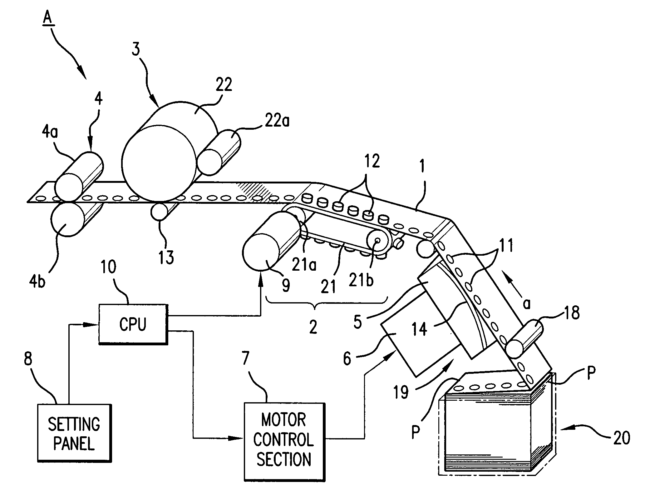
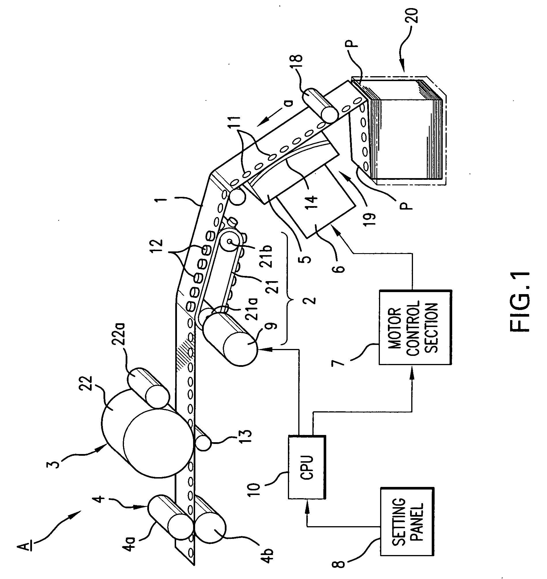
[0036]FIG. 1 is a perspective view showing a continuous paper feeding device as the present invention. In FIG. 1, continuous paper feeding device A is incorporated in a laser printer. The continuous paper feeding device A comprises a paper supply section 20 as a paper supply device, a feeding section 2 adapted to feed a continuous printing paper sheet 1 supplied from the paper supply section 20, a printing device 3 disposed downstream of the feeding section 2, a fusing section 4 located downstream of the printing device 3, a braking device 19 disposed upstream of the feeding section 2, a motor control section 7 for controlling a fan motor of the braking device 19, and a CPU 10 for controlling each section.

[0037] The paper supply section 20 accommodates the printing paper sheet 1 in a folded state, the paper sheet 1 having perforated lines P along which the paper sheet 1 can be cut at predetermined longitudinal intervals.

[0038] When the printing paper sheet 1 (set on the feeding sec...

second embodiment

[0066]FIG. 9 illustrates a continuous paper feeding device as the present invention. Like or corresponding parts are designated by like reference numbers throughout FIGS. 1 and 9 to avoid repetition of description thereof.

[0067] While the embodiment shown in FIG. 1 is configured to set a braking force to be applied by the braking device 19 according to data input from the setting panel by the user, the embodiment shown in FIG. 9 is configured to cause the CPU to set a braking force automatically.

[0068] Specifically, continuous paper feeding device A (shown in FIG. 9) is provided with a sensor 23 for judging whether a paper sheet is passing and detecting sheet width W, a sensor 24 for detecting the distance up to a paper sheet and determining sheet thickness t based on the distance thus detected, and a sensor 25 for detecting the humidity of the atmosphere around the printer-installed site. CPU 10 establishes a braking force by making synthetic judgment from all the results output f...

third embodiment

[0071]FIG. 10 illustrates a continuous paper feeding device incorporating a braking device 39 of a different type as the present invention. Like or corresponding parts are designated by like reference numbers throughout FIGS. 1 and 10 to avoid repetition of description thereof.

[0072] The braking device 39 shown in FIG. 10 comprises a pair of braking rollers 31 and 32 located upstream of the feeding section 2 and holding printing paper sheet 1 therebetween from its obverse and reverse sides. The braking roller 31 is freely rotatable as the printing paper sheet 1 moves. The braking roller 32 is connected to an electromagnetic brake 33 for imposing a load on the braking roller 32 rotating. The electromagnetic brake 33 varies the load on the braking roller 32 according to its electromagnetic force varied by a current control circuit 43 controlling the amount of electric current.

[0073] With this arrangement, CPU 10 selects a braking force according to a set brake value established throu...


PUM


Abstract

A tractor feeds a perforated continuous paper sheet to a printing position. The feeding force of a fusing device located downstream of the printing position is set larger than the feeding force of the tractor in order to apply tension to the continuous paper sheet at the printing position. A braking device located upstream of the tractor applies a braking force balancing with the feeding force of the fusing device to the continuous paper sheet. The braking force of the braking device is varied depending upon the properties of the paper sheet or the environmental conditions. This arrangement makes it possible to stabilize the feeding state even under situations where the sheet feeding force is likely to become unstable, thereby realizing printing without any deviation from the predetermined position. Further, this arrangement can also prevent hole breakage to occur.

Description

RELATED APPLICATIONS [0001] The present application claims priority to Japanese Patent Application No. 2000-259553 filed Aug. 29, 2000, the entire content of which is hereby incorporated by reference. TECHNICAL FIELD OF THE INVENTION [0002] This invention relates to continuous paper feeding devices for feeding continuous paper sheets, and in particular, to printers for printing images on perforated printing paper sheets. BACKGROUND OF THE INVENTION [0003] Conventional printers adapted for printing on continuous paper sheets employ a tractor feeder which is capable of horizontally feeding printing paper sheets as a feeding device for feeding continuous paper sheets in order to realize their downsizing. The tractor feeder is configured to feed a printing paper sheet by causing feed pins of a rotary-driven endless tractor to sequentially engage perforations arranged with a predetermined pitch longitudinally of the printing paper sheet. [0004] As is often the case with such continuous p...

Claims


Application Information

Patent Timeline
IPC IPC(8): B41J15/00B65H1/00B65H5/00B41J11/30B65H20/20B65H23/10B65H23/24
CPCB65H23/245B65H20/20B65H2220/02B65H2220/04B65H2404/143B65H2406/31B65H2511/12B65H2701/11231B65H2515/31
Inventor MIURA, KUNIYUKITODA, MASAHIROITO, TAKAYUKIHONAGA, HIRONAOOOMOTO, NOBORU
Owner MINOLTA CO LTD
Why Eureka
Try Eureka