Al technical title is built by PatSnap Al team. It summarizes the technical point description of the patent document.
A backlight module and display technology, applied in the direction of static indicators, optics, instruments, etc., can solve the problems of light leakage, inconvenient assembly, easy light leakage, etc., and achieve the effect of improving assembly efficiency and reducing the probability of light leakage
Inactive Publication Date: 2009-07-15
AU OPTRONICS CORP
View PDF6 Cites 0 Cited by
Summary
Abstract
Description
Claims
Application Information
AI Technical Summary
This helps you quickly interpret patents by identifying the three key elements:
Problems solved by technology
Method used
Benefits of technology
Problems solved by technology
[0002] see figure 1 , the existing backlight module 10 includes a base plate 11, a diffuser plate 12, support units 13a, 13b, 13c, and a light source 14, and the support units 13a, 13b, 13c are arranged on the base plate 11 to support the diffuser plate 12 and isolate the light emitting Areas A, B, and C, however, when the backlight module 10 is operating, the luminous areas A, B, and C do not necessarily emit light at the same time (that is, a black screen will be inserted into the luminous areas A, B, and C), at this time, If the supporting units 13a, 13b, 13c do not have special light guide design, light leakage may occur. If the support units 13a and 13b do not have special light guide design, the light in the light emitting regions A and C will easily leak to the light emitting region B where the black screen must be kept, which will cause the contrast of the backlight module 10 to decrease, and the display effect will also be reduced. with decreasing
[0003] In addition, the existing backlight module 10 does not provide a special structure for assembling the bottom plate 11 and the circuit board 15, so the circuit board 15 may be fixed on the bottom plate 11 by locking, causing inconvenience in assembly.
Method used
Image
Click on the blue label to locate the original text in one second.
Reading with bidirectional positioning of images and text.
Examples
Embodiment Construction
[0044] In order to make the above and other objects, features and advantages of the present invention more comprehensible, preferred embodiments are specifically listed below and described in detail in conjunction with the accompanying drawings.
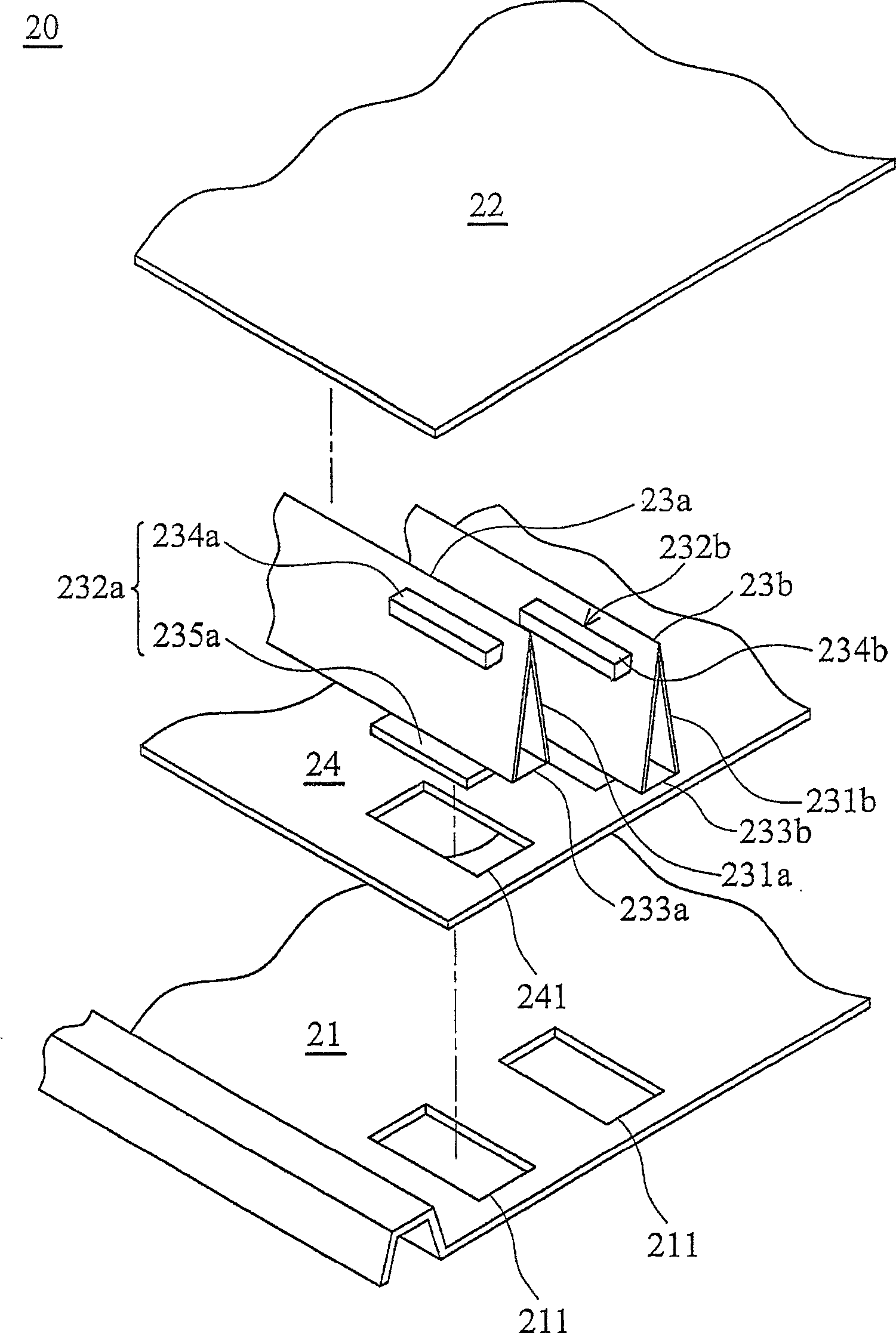
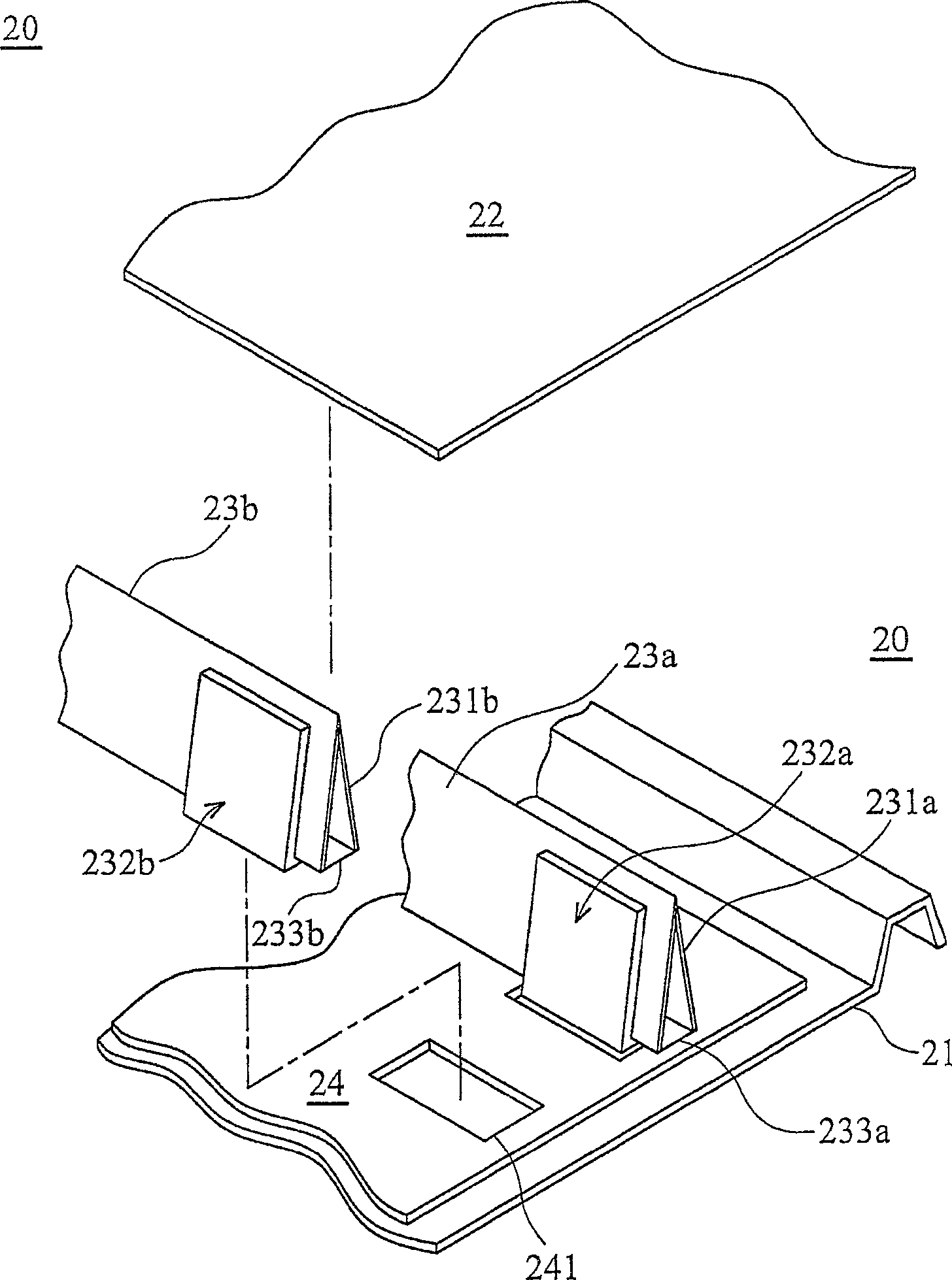
[0045] see figure 2 , 3 The backlight module 20 of the present invention includes a bottom plate 21, a diffusion plate 22, support units 23a, 23b, and a circuit board 24. The circuit board 24 is arranged on the bottom plate 21 and includes at least one positioning hole 241, and the bottom plate 21 is also provided with There are positioning holes 211, and when the circuit board 24 overlaps with the bottom plate 21, the positioning holes 241 and the positioning holes 211 overlap each other, and the support units 23a, 23b include reflective parts 231a, 231b and engaging parts 232a, 232b. The parts 232a, 232b fix the supporting units 23a, 23b on the bottom plate 21 and the circuit board 24. It should be noted that the engaging parts 2...
PUM
Abstract
The invention discloses a display and a backlight module thereof. The backlight module includes a base plate, a diffuser plate, at least one support unit and at least two light sources, the support unit includes a reflective part and an engaging part, the engaging part is U-shaped and includes a fixing part, and the fixing part passes through the supporting unit. The engaging part is hung on the support unit, or the engaging part is L-shaped and directly extends downward from the support unit, and the backlight module is divided into at least two light-emitting areas by the support unit arranged between the bottom plate and the diffuser plate, The light sources are respectively arranged in these light-emitting areas, and the light emitted by the light sources located in these light-emitting areas is blocked by the supporting unit and combined with the light-guiding effect of the reflector, which can effectively reduce the probability of light leakage. The display includes the above-mentioned backlight module and For the panel, the light from the light source will be transmitted to the panel after passing through the backlight module. The invention can reduce the probability of light leakage and improve assembly efficiency.
Description
technical field [0001] The invention relates to a display and a backlight module thereof. Background technique [0002] see figure 1 , the existing backlight module 10 includes a base plate 11, a diffuser plate 12, support units 13a, 13b, 13c, and a light source 14, and the support units 13a, 13b, 13c are arranged on the base plate 11 to support the diffuser plate 12 and isolate the light emitting Areas A, B, and C, however, when the backlight module 10 is operating, the luminous areas A, B, and C do not necessarily emit light at the same time (that is, a black screen will be inserted into the luminous areas A, B, and C), at this time, If the supporting units 13a, 13b, 13c do not have special light guide design, light leakage may occur. If the support units 13a and 13b do not have special light guide design, the light in the light emitting regions A and C will easily leak to the light emitting region B where the black screen must be kept, which will cause the contrast of t...
Claims
Application Information
Patent Timeline
Application Date:The date an application was filed.
Publication Date:The date a patent or application was officially published.
First Publication Date:The earliest publication date of a patent with the same application number.
Issue Date:Publication date of the patent grant document.
PCT Entry Date:The Entry date of PCT National Phase.
Estimated Expiry Date:The statutory expiry date of a patent right according to the Patent Law, and it is the longest term of protection that the patent right can achieve without the termination of the patent right due to other reasons(Term extension factor has been taken into account ).
Invalid Date:Actual expiry date is based on effective date or publication date of legal transaction data of invalid patent.