Light guide lamp for vehicle

A technology of light guides and lamps, which is applied in the direction of light guides, light guides of lighting systems, semiconductor devices of light-emitting elements, etc., can solve the problems of long light guide structure, light leakage, and inability to achieve visual effects, etc., to reduce difficulty, reduce cost, and reduce processing effect of error

Active Publication Date: 2016-02-03
CHONGQING CHANGAN AUTOMOBILE CO LTD
View PDF6 Cites 0 Cited by
  • Summary
  • Abstract
  • Description
  • Claims
  • Application Information

AI Technical Summary

Problems solved by technology

Since the patent is provided with light guide teeth and two light collection surfaces 7, for a light guide structure with a larger diameter, a uniform visual effect is achieved on the basis of reducing the number of LED lights and the light utilization rate is high; but This patent achieves the homogenization effect by performing multiple internal total reflections in the light guide structure 5. In order to achieve the purpose of homogenization, the required light guide structure is relatively long, and its homogenization effect is limited by the length of the light guide structure. The small-diameter light guide structure cannot achieve a uniform visual effect. At the same time, the sawtooth-shaped light guide teeth 6 have a small angle between adjacent teeth. If the LED light source has size and assembly tolerances, the light incident into the light guide structure The light has a certain diffusion angle, and the sawtooth-shaped light guide tooth surface cannot constitute a total reflection condition, and the light will be refracted from the inner and outer sides of the light guide structure 5, resulting in light leakage, especially after the introduction of processing errors in the mold and injection molding process , the tip of the serrated light guide tooth will have a chamfer, which will increase the light leakage

Method used


Image

  • Light guide lamp for vehicle
  • Light guide lamp for vehicle
  • Light guide lamp for vehicle

Examples


Embodiment Construction

[0030] The present invention will be further described below in conjunction with the drawings.

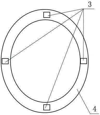
[0031] In this embodiment, the diameter of the light guide ring of the vehicle light guide lamp is 40 mm.

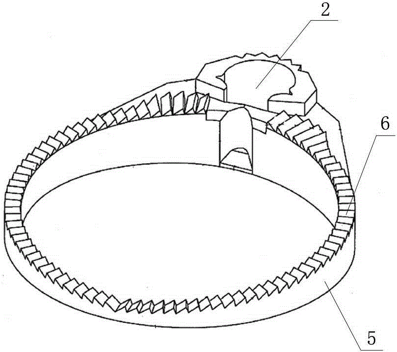
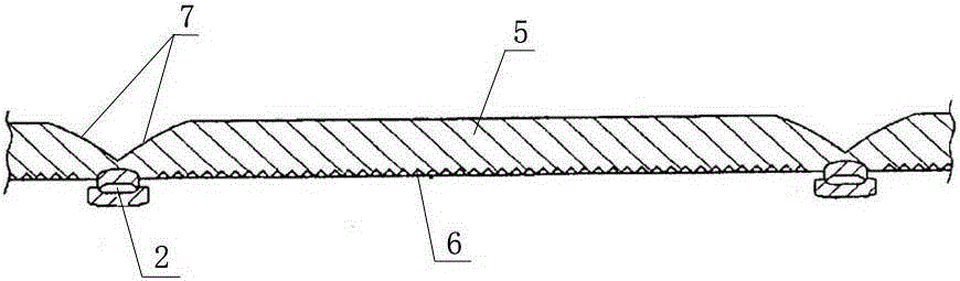
[0032] Such as Figure 1 to Figure 10 The car light guide lamp shown includes a light guide ring 1 and an LED light source 2. The light guide ring 1 is formed by one-time injection molding of PC plastic with titanium oxide added. The LED light source 2 is composed of a single LED lamp, and the LED lamp is a lens. For packaged SMD LEDs, the light emitted by the LED light source 2 enters the light guide ring 1; the top of the light guide ring 1 has two light collection surfaces 11 and a flat light exit surface 12, and the bottom is a toothed reflection surface 13; The light collecting surface 11 is a parabolic surface with the plane where the LED light source 2 is located as the main axis. The two light collecting surfaces 11 have a common focal point and are connected symmetricall...


PUM


Abstract

The invention discloses a light guide lamp for an automobile. The light guide lamp comprises a light guide circular ring and a light-emitting diode (LED) light source, wherein the light emitted by the LED light source enters the light guide circular ring; the top of the light guide circular ring is provided with two light collecting surfaces and a flat light emitting surface, and the bottom of the light guide circular ring is a tooth-shaped reflecting surface; the tooth-shaped reflecting surface is formed by connecting a plurality of step-shaped light guide teeth with equal superficial area; each light guide tooth is provided with a tooth plane parallel to the plane where the LED light source is arranged, and a tooth inclined plane, wherein the included angle between the tooth inclined plane and the tooth plane is 130-140 degrees; the heights of the tooth inclined planes of the light guide teeth are not consistent with one another; the light intensities of light rays which are emitted by the light emitting surface after being reflected by the tooth inclined planes of all the light guide teeth are equivalent. After the light guide lamp is adopted, the light leakage probability is reduced, the light utilization rate is increased, the visual effect of a uniform light ring with smaller diameter can be realized, and the cost is lowered.

Description

Technical field [0001] The invention relates to a lamp for a vehicle, in particular to a light guide lamp for outdoor, indoor and background light indicators of a car. Background technique [0002] In order to make the car's outdoor position lights, indoor knob indicators, etc. form a circular ring of human eye lighting effects, the traditional approach (see figure 1 ) Is to use multiple LED lights 3 for ring arrangement. Generally, four or six LED lights 3 are uniformly arranged in the ring area in the area where the ring lighting effect is required. The light emitted by these LED lights directly illuminates the diffuse On the reflective ring-shaped matching structure 4, through the diffuse reflection of the ring-shaped matching structure 4, the human eye can observe a ring-shaped aperture; however, the position of the aperture near the LED lamp has higher brightness than the position far away from the LED lamp, and the entire aperture is visually viewed Non-uniformity. Generall...

Claims


Application Information

Patent Timeline
Patent Type & Authority Patents(China)
IPC IPC(8): F21S8/10F21V8/00F21W101/02F21Y101/02F21W107/10F21Y115/10
Inventor 周霞万宏丁小兵王晋委徐涛
Owner CHONGQING CHANGAN AUTOMOBILE CO LTD
Why Eureka
Try Eureka