Suction cup structure

A suction cup, disc body technology, applied in suction cups, connecting components, mechanical equipment, etc.

Active Publication Date: 2009-08-19
MITAC COMP (SHUN DE) LTD +1
View PDF4 Cites 4 Cited by
  • Summary
  • Abstract
  • Description
  • Claims
  • Application Information

AI Technical Summary

Problems solved by technology

[0002] At present, the fixing seats of electronic products (such as mobile phones, personal digital assistants or navigation devices) connected inside and outside the car are usually clamped to the position of the air-conditioning outlet or the car cigarette lighter by clips, but the actual use may vary depending on the model , not every car can use the position of the fixed seat so that the user can clearly see the screen information of the electronic product

Method used


Image

  • Suction cup structure
  • Suction cup structure
  • Suction cup structure

Examples


Embodiment Construction

[0016] In order to make the above-mentioned purposes, features, and advantages of the present invention more obvious and easy to understand, a preferred embodiment of the sucker structure according to the present invention will be cited below, and it will be described in detail as follows in conjunction with the accompanying drawings, wherein the same elements Description will be made with the same reference numerals.

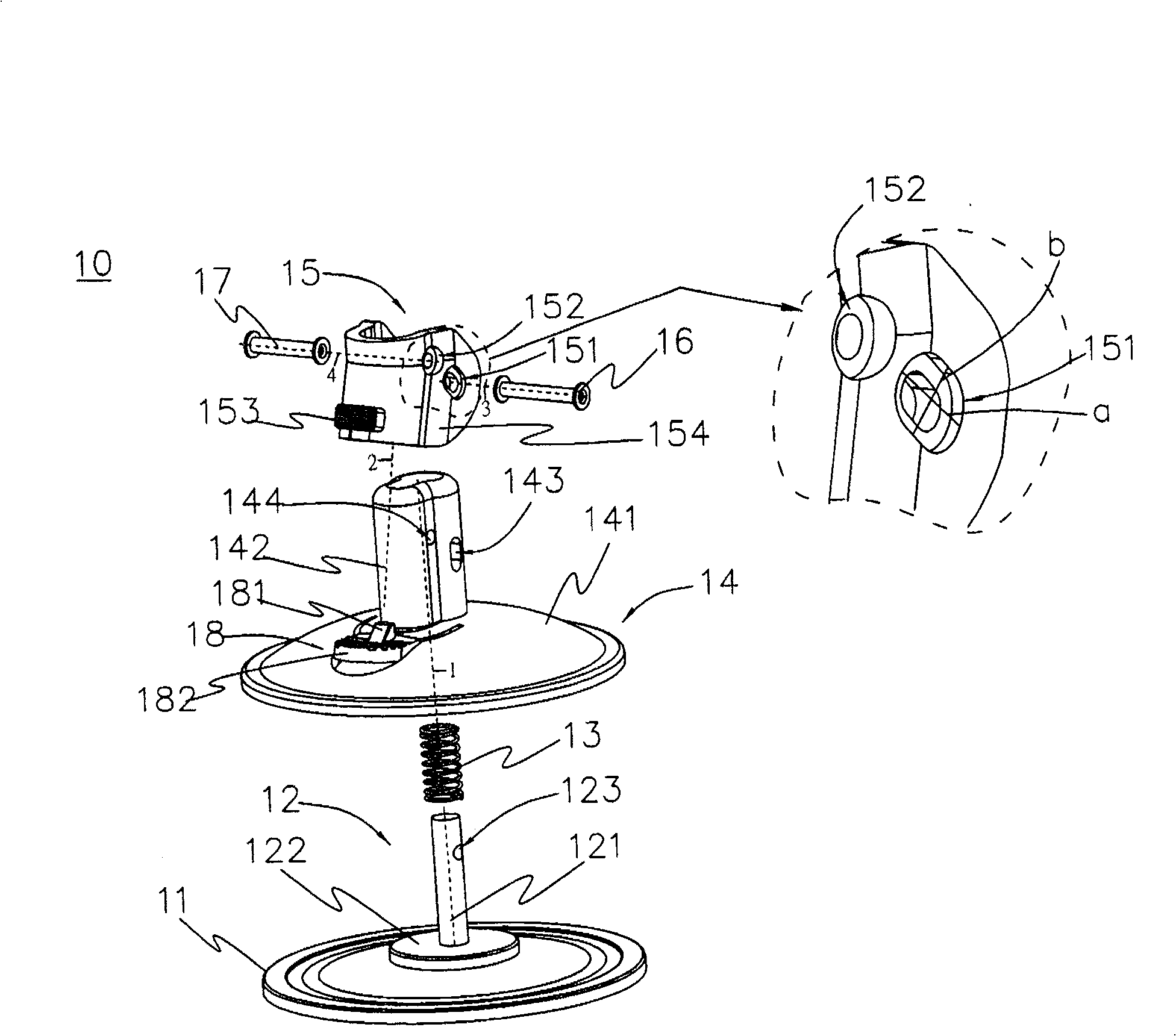
[0017] see figure 1 , which is a three-dimensional exploded view of the sucker structure of the present invention. In the figure, this suction cup structure 10 comprises suction cup 11, pull rod 12, spring 13, bracket seat 14, button arm 15, slide pin 16 and shaft pin 17, wherein, suction cup 11 is plate-shaped and slightly flexible, and pull rod 12 has A rod body 121 and a disc 122, one end of the rod body 121 is vertically connected to the center of the disc 122, and the disc 122 is embedded in the sucker 11 (see Figure 5 or Figure 9 ), and the rod body ...


PUM


Abstract

The invention provides a sucker structure, comprising a sucker, a pull rod, a bracket base, a sliding pin, a button swivel, and a shaft pin; wherein, the pull rod is vertically connected with the sucker and is provided with a horizontal penetrated through hole, a sleeve of the bracket base is provided with a horizontal penetrated rotating shaft hole and a sliding groove; the pull rod is positioned in the sleeve of the bracket base, and the sucker is positioned under a sucker body of the bracket base. The sliding pin passes through the sliding groove, the through hole and a first hole of the button swivel, and the shaft pin passes through a rotating shaft hole and a second hole of the button swivel. By pressing a button end of the button swivel, a braking piece of the button swivel can rotate around the shaft pin which acts as a fulcrum, thus pulling the sliding pin to ensure that the sliding pin slides from the lower end of the first hole to the upper end thereof, and at the same time slides in the sliding groove to jointly pull the pull rod, therefore, the sucker is lifted and enhanced and generates the sucking function.

Description

technical field [0001] The invention relates to a suction cup structure, in particular to a suction cup structure for pulling up a pull rod to make the suction cup produce an adsorption function. Background technique [0002] At present, the fixing bases of electronic products (such as mobile phones, personal digital assistants or navigation devices) connected inside and outside the car are usually clamped to the position of the air-conditioning outlet or the car cigarette lighter by clips, but the actual use may vary depending on the model However, not every car is positioned so that the user can clearly see the screen information of the electronic product when using the fixed seat. Therefore, if the glass on the car can be utilized and a connecting rod structure with a suction cup can be used, another option for the user can be provided to adjust it to a position most suitable for the user to watch. [0003] In order to meet the above mentioned usage requirements. Based ...

Claims


Application Information

Patent Timeline
Patent Type & Authority Patents(China)
IPC IPC(8): F16B47/00
Inventor 游林坚
Owner MITAC COMP (SHUN DE) LTD
Why Eureka
Try Eureka