Vibration isolation structure of optical disk drive
A CD drive, vibration isolation technology, applied in the direction of poor vibration/sound insulation/absorption, etc., can solve problems such as easy to shake up and down, easy to grind to the tray base, etc.
- Summary
- Abstract
- Description
- Claims
- Application Information
AI Technical Summary
Problems solved by technology
Method used
Image
Examples
Embodiment 1
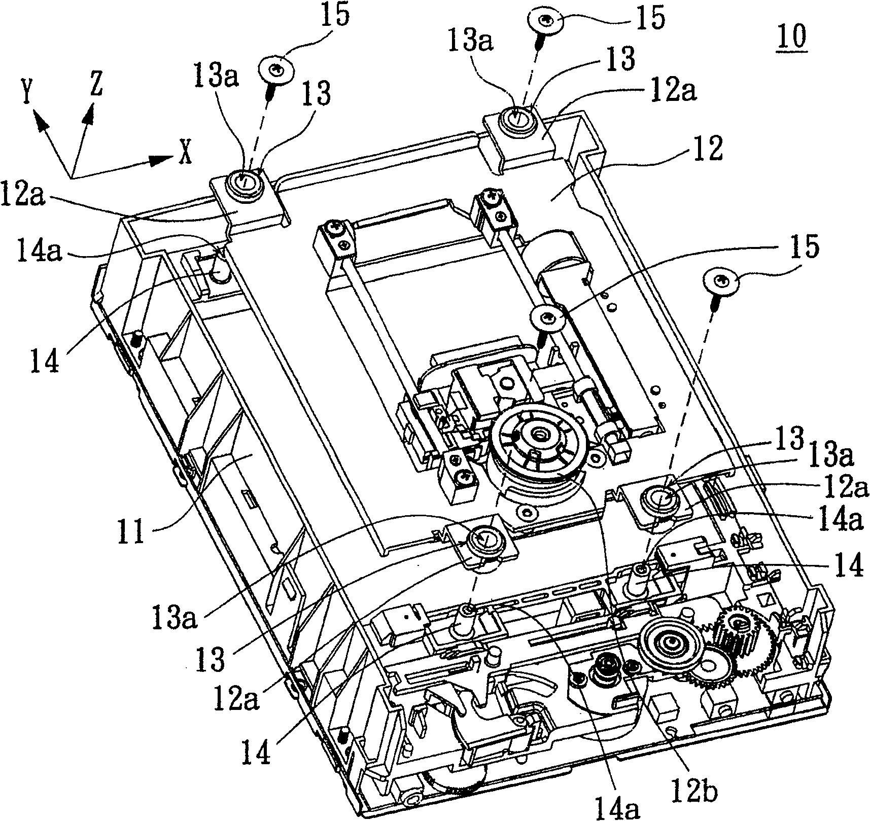
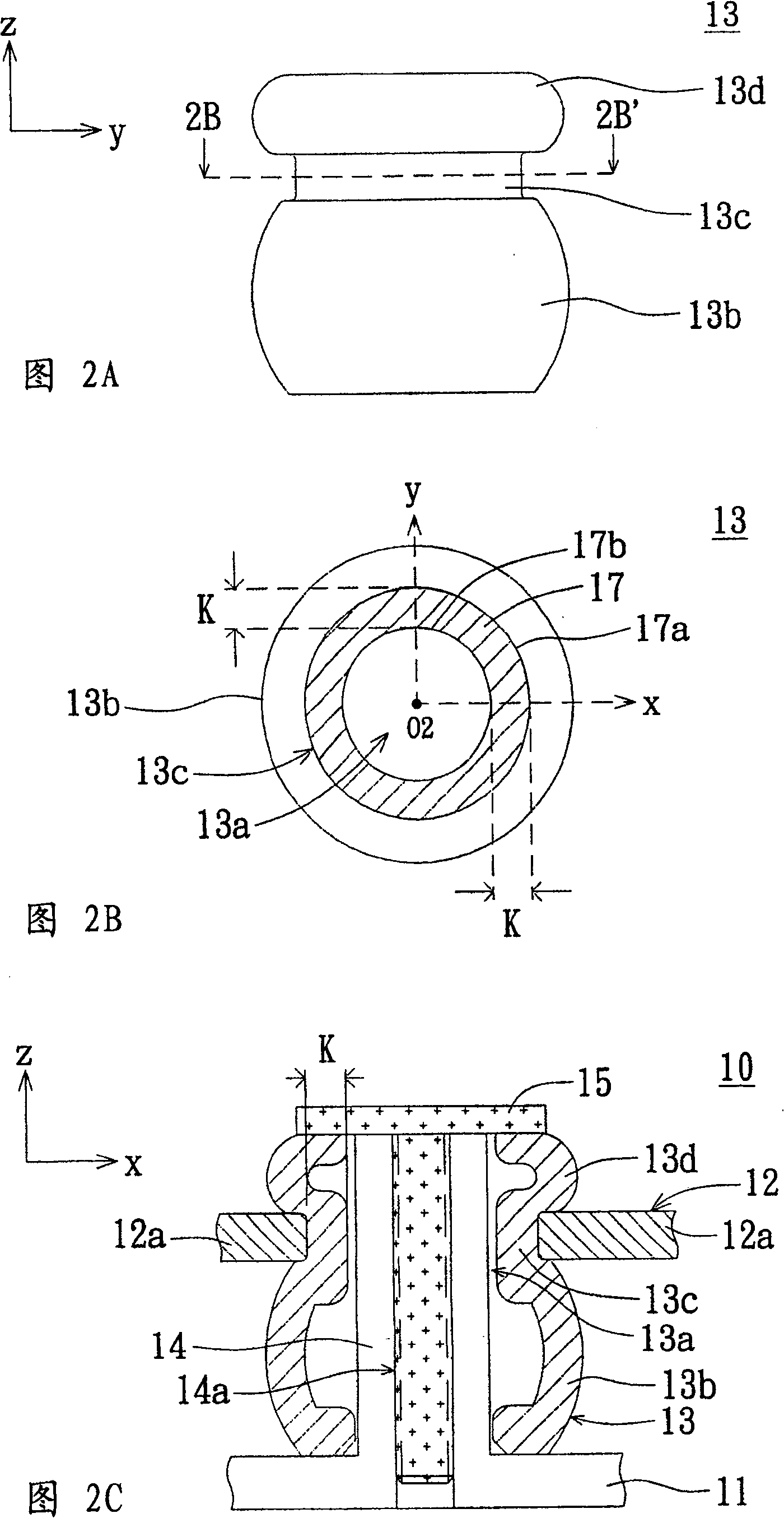
[0063] refer to Figures 4A-4B , Figure 4A It is an exploded perspective view showing a partial structure of an optical disc drive with an optical disc drive vibration isolation structure according to Embodiment 1 of the present invention, Figure 4B yes means Figure 4A The exploded and enlarged perspective view of the vibration isolation structure of the movement and optical disk drive. exist Figures 4A-4B Among them, the optical disc drive 40 includes a base 41, a core 42 and at least one optical disc drive vibration isolation structure 43, the optical disc drive vibration isolation structure 43 is arranged between the base 41 and the core 42, the optical disc drive vibration isolation structure 43 has A through hole 43a. The base 41 has at least one set of fixing columns 44 for inserting into the through holes 43 a so that the vibration isolation structure 43 of the optical disk drive is fixed on the base 41 . In addition, the opening shape of the through hole 43 a ...
Embodiment 2
[0073] refer to Figures 7A-7B , Figure 7A It is an enlarged side view showing the vibration isolation structure of the optical disk drive according to the second embodiment of the present invention, Figure 7B means along Figure 7A The sectional view of the vibration isolation structure of the optical disk drive viewed by the sectional line 7B-7B'. exist Figures 7A-7B Among them, the optical disc drive vibration isolation structure 53 at least includes a bottom 53b, a neck 53c and a top 53d, the neck 53c connects the bottom 53b and the top 53d, and the bottom 53b, neck 53c and top 53d have a through hole 53a. The through hole 53 a penetrates the top surface of the top 53 d and the bottom surface of the bottom 53 b along a central line L1 , and the extending direction of the central line L1 is the z direction.
[0074]The difference between the vibration isolation structure 53 of this embodiment and the vibration isolation structure 43 of Embodiment 1 lies in the way of...
Embodiment 3
[0076] refer to Figures 8A-8B , Figure 8A It is an enlarged side view showing the vibration isolation structure of the optical disc drive according to the third embodiment of the present invention, Figure 8B is to mean along Figure 8A The cross-sectional view of the vibration isolation structure of the optical disk drive viewed by the section line 8B-8B'. Compared with the vibration isolation structure 53 of the second embodiment, the vibration isolation structure 63 of this embodiment has at least one positioning rib 55a, and this embodiment will take two positioning ribs 55a as an example for illustration. exist Figures 8A-8B Among them, the two positioning ribs 55a are symmetrically disposed on the outer surface of the portion of the neck 53c along the extending direction passing through the central line L1, and extend on the outer surfaces of the portion of the bottom 53b and the top 53d. In addition, the positioning ribs 55a protrude symmetrically outside the nec...
PUM
 Abstract
Description
Claims
Application Information
 - R&D
- Intellectual Property
- Life Sciences
- Materials
- Tech Scout
- Unparalleled Data Quality
- Higher Quality Content
- 60% Fewer Hallucinations
Browse by: Latest US Patents, China's latest patents, Technical Efficacy Thesaurus, Application Domain, Technology Topic, Popular Technical Reports.
© 2025 PatSnap. All rights reserved.Legal|Privacy policy|Modern Slavery Act Transparency Statement|Sitemap|About US| Contact US: help@patsnap.com


