Vertical life refuse heat decomposition incinerator

A domestic garbage and incinerator technology, applied in the field of incinerators, can solve the problems of low water seal of the slag extractor, insufficient use of waste heat, unstable combustion, etc., and achieve the effect of small maintenance, low failure rate, and improved site environment

Inactive Publication Date: 2009-10-14
深圳京基环保设备有限公司
View PDF4 Cites 1 Cited by
  • Summary
  • Abstract
  • Description
  • Claims
  • Application Information

AI Technical Summary

Problems solved by technology

Its shortcomings are: firstly, lack of pre-drying of garbage into the furnace, and unstable combustion; secondly, insufficient utilization of waste heat; thirdly, low water seal requirements of the slag discharge machine, which makes it difficult to overcome the wind pressure of the air inlet pipe

Method used


Image

  • Vertical life refuse heat decomposition incinerator
  • Vertical life refuse heat decomposition incinerator

Examples


Embodiment 1

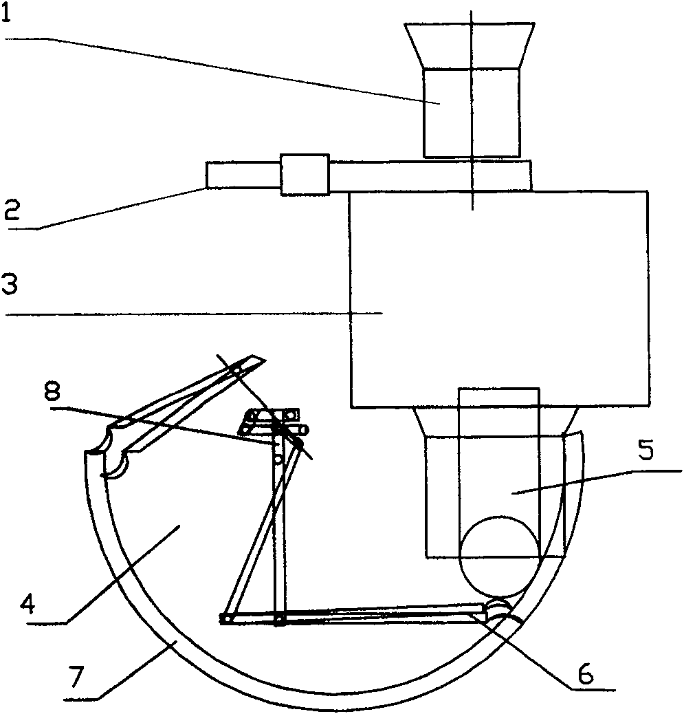
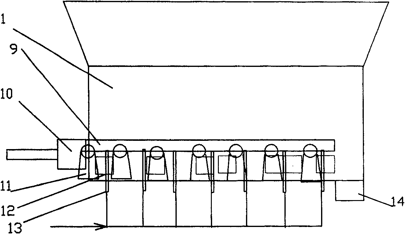
[0024] Example 1 in figure 1 , 2 Among them, a vertical domestic waste thermal decomposition incinerator, including an incinerator body 3, a hopper and a feeding bin 1 at the front end of the incinerator body 3, and a slagging device 4 at the rear end; it is characterized in that: in the hopper and the feeding bin 1 The stepping feeding device 2 is set at the end; the described feeding device 2 is a stepping conveyor, mainly consisting of a conical hopper, a trough, a horizontal stepping plate 12, a hydraulic drive device 10 and a hot air drying chamber 13; the horizontal stepping The top of the feeding plate 12 is connected to the conical hopper 1, and the bottom is provided with a hot air drying chamber 13; the horizontal stepping plate 12 is connected with the push rod mechanism 9 on the roller bracket 11 and driven by the hydraulic drive device 10, and the garbage is pushed in and out step by step. Material mouth 14. In view of the problem that the 100t / d vertical therma...

Embodiment 2

[0026] Embodiment 2 A vertical domestic waste pyrolysis incinerator, wherein the hot air drying chamber 13 is connected to the flue gas air preheater in the tail flue of the boiler body of the incinerator with pipelines, and the drying hot air is introduced. All the other are with embodiment 1. The waste heat of the flue gas is used to heat the cold air, and the heated hot air is supplied to the walking garbage conveyor. Hot air can be used as its backup hot air source. Using the waste heat of the flue gas can reduce the exhaust gas temperature and improve the efficiency of the boiler.

Embodiment 3

[0027] Embodiment 3 A vertical domestic waste thermal decomposition incinerator, wherein the slag removal device 4 adopts a hydraulic bucket arm type slag remover; its structure is that the bottom of the air inlet pipe 5 is water-sealed at the bottom of the tank 7 below the outlet of the ash hopper A dust-scraping board 6 is set, and the dust-scraping board 6 is driven by a bucket arm type connecting rod transmission mechanism 8 . like figure 1 shown. General waste incineration devices such as grate furnaces and circulating fluidized bed furnaces use hydraulic arc-shaped push plate slag machines or chain plate slag machines. Because the vertical rotary pyrolysis waste incinerator has a conical ash hopper at the lower part of the furnace body inserted into the water seal tank, and the primary air pipe of the first combustion chamber passes through the center of the conical ash hopper and then enters the air under the rotary grate. chamber, the slag falls into the water from t...


PUM


Abstract

The invention discloses a vertical domestic waste thermal decomposition incinerator, which comprises an incinerator body, a hopper and a feeding bin at the front end of the incinerator body, and a slag discharging device at the rear end; a feeding device is arranged at the rear end of the hopper and the feeding bin; The feeding device described above is a stepping type, mainly composed of a conical hopper, a trough, a horizontal stepping plate, a hydraulic drive device and a hot air drying chamber; room; the horizontal stepping plate is driven by a hydraulic drive device, and the garbage is pushed into the discharge port in a step-by-step manner. The hot air drying chamber is connected to the flue gas air preheater in the tail flue of the boiler of the incinerator body with pipelines. The slag discharge device adopts a hydraulic bucket arm type slag discharge machine; its structure is to set a dust scraper at the bottom of the water seal groove at the bottom of the air inlet pipe under the outlet of the ash hopper, and the dust scraper is driven by the bucket arm linkage transmission mechanism. It is suitable for waste incinerators with high moisture content and low calorific value.

Description

technical field [0001] The invention relates to an incinerator in energy and environmental protection equipment, in particular to a domestic garbage incinerator. It can be especially used for incineration of low calorific value, high moisture, unsorted household waste incineration to generate electricity. Background technique [0002] With the development of modern production, the increase of urban population and the improvement of consumption level, the generated garbage pollutes the environment and causes social public hazards, which has already attracted the attention of all countries. At present, there are two major types of municipal solid waste disposal methods, namely incineration and sanitary landfill. The latter occupies a large amount of land and its leachate pollutes more groundwater, and the landfill causes secondary pollution to the surrounding environment. Most foreign countries use waste incineration to achieve the purpose of reduction, harmlessness and reso...

Claims


Application Information

Patent Timeline
Patent Type & Authority Patents(China)
IPC IPC(8): F23G5/02
Inventor 请求不公开姓名
Owner 深圳京基环保设备有限公司
Why Eureka
Try Eureka