Needle for a loop-forming system

一种线圈、构件的技术,应用在构成线圈的系统领域,能够解决止挡住、或挂住或摩擦等问题,达到细针距的效果

Inactive Publication Date: 2009-12-02
GROZ BECKERT KG
View PDF5 Cites 0 Cited by
  • Summary
  • Abstract
  • Description
  • Claims
  • Application Information

AI Technical Summary

Problems solved by technology

In addition, there is the danger that the closure section catches, catches or rubs against the hook point when passing the fork-shaped hook point when the side play is minimal.

Method used


Image

  • Needle for a loop-forming system
  • Needle for a loop-forming system
  • Needle for a loop-forming system

Examples


Embodiment Construction

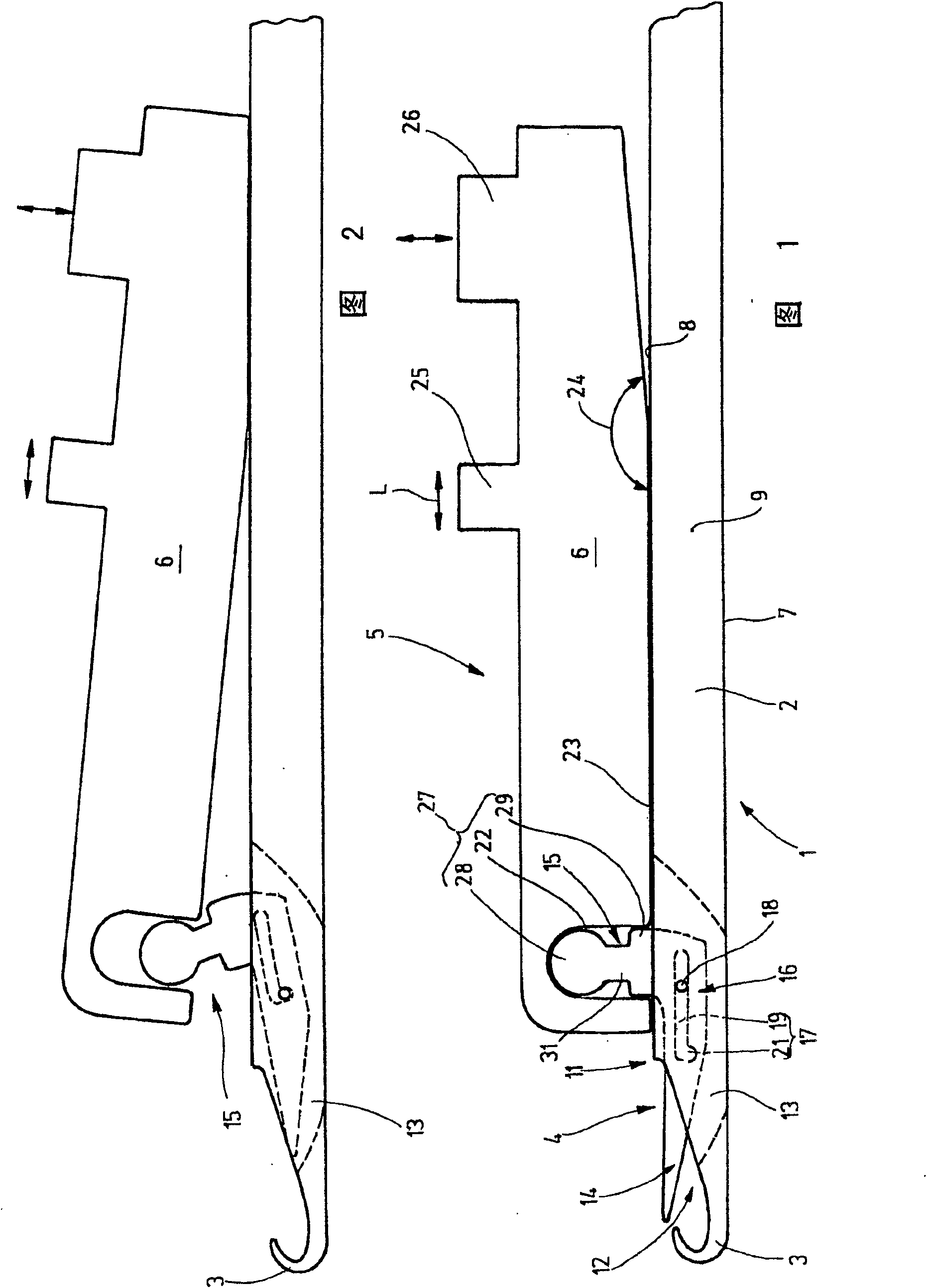
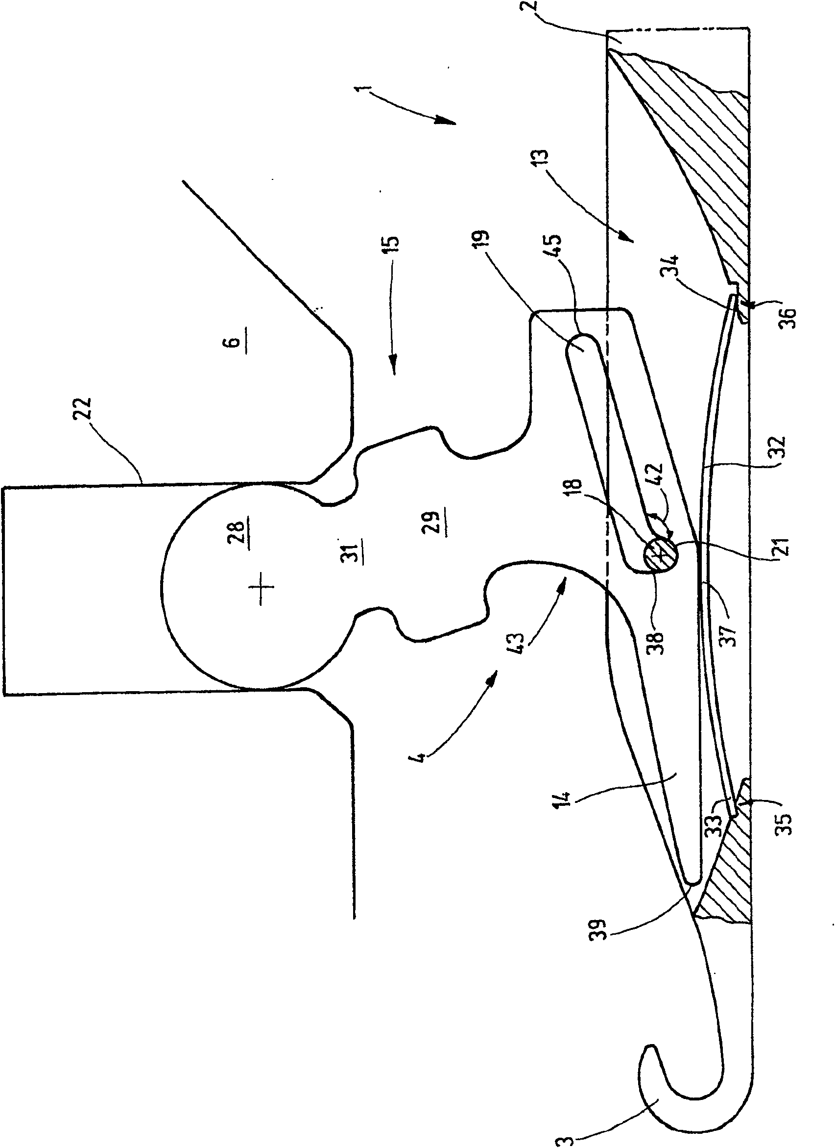
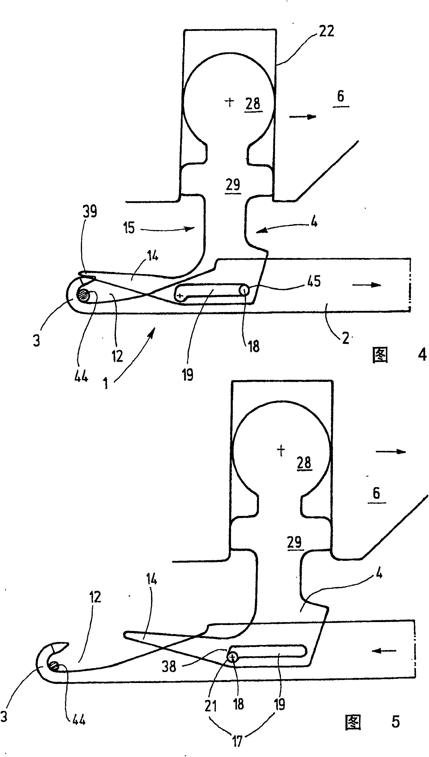
[0022] figure 1 A needle 1 is shown, which may be a machine needle, for example, on a circular knitting machine. Associated with this needle 1 is a needle body 2 which has a hook 3 formed on the end side and a closure element 4 which is supported on the needle body 2 . In addition, the needle 1 is equipped with a control board 6 as control member 5 .

[0023] The needle body 2 is a flat body, for example with a straight narrow needle back 7, an equally narrow straight needle upper side 8 and preferably flat sides between them, in which the figure 1 Only one side is visible in 9. Since this cross-section of the needle body 2 is substantially uniform, it has a step 11 in the vicinity of the hook 3, from which step the height of the needle body 2 decreases towards the hook 3. The entire cavity defined by the hook 3 and the step 11 is used for loop forming. This is referred to here as the hook cavity 12 .

[0024] The needle body 2 is provided with a groove 13 which starts ap...


PUM


Abstract

The invention relates to a needle for a system of forming loops, the needle having a needle body at the end of which a hook is formed and a closure member which is slidable and also capable of At least one slide point is pivotally mounted on the needle, wherein the closure element has a control section which engages with a control element. According to the invention, the control element is a control plate, wherein a controllable connection is provided between the control plate and the control section, wherein the closing element (4) is guided by means of a slide (16) hold on. The invention also relates to a needle for a system of forming loops, the needle having a body at the end of which a hook is formed and a closure member which is slidable and also capable of Mounted pivotally on the needle in at least one sliding position, according to the invention the closure member is supported by means of a slide guide.

Description

technical field [0001] The invention relates to a system for forming loops, in particular a needle for a knitting system. Background technique [0002] Needles of systems for forming loops, such as knitting machine needles, generally have a base body with a shank and a hook arranged on the needle shank, wherein the hook cavity can be opened and closed by a suitable closure element. For example, a pivotally mounted tongue or a sliding rod mounted slidably along the needle is used as the closure element. The slide bar of a compound needle is provided with a butt which engages with a triangular key so that the opening and closing movements can be controlled in a controlled manner. The slider goes through a considerable amount of travel. [0003] There are latch needles in which the latch is supported freely movable. In addition, known some latch needles, its tongue movement is controlled by a control slide bar. One such latch needle is known from WO 00 / 34560. Such a latch ...

Claims


Application Information

Patent Timeline
Patent Type & Authority Patents(China)
IPC IPC(8): D04B35/06
CPCD04B35/06D04B35/04D05B85/14
Inventor R·西门丁格K·维登赫菲尔M·绍特
Owner GROZ BECKERT KG
Why Eureka
Try Eureka