Stirring feet including drive shaft driven in rotation by motorized housing

A technology of stirring feet and drive shafts, applied in the field of stirring feet, can solve the problems of inability to change the gap and expensive implementation, and achieve the effect of economical implementation, small positioning and simple implementation

Active Publication Date: 2021-07-30
SEB SA
View PDF10 Cites 0 Cited by
  • Summary
  • Abstract
  • Description
  • Claims
  • Application Information

AI Technical Summary

Problems solved by technology

This technical solution therefore has the disadvantage that it is expensive to implement
[0005] In addition, with this technical solution, the gap between the elastic ring and the bearing varies according to the manufacturing dispersion, and the gap cannot be changed

Method used


Image

  • Stirring feet including drive shaft driven in rotation by motorized housing
  • Stirring feet including drive shaft driven in rotation by motorized housing
  • Stirring feet including drive shaft driven in rotation by motorized housing

Examples


Embodiment Construction

[0038] Only elements necessary for understanding the invention are shown. For the convenience of reading the drawings, the same elements are given the same reference numerals in different drawings.

[0039] And it is worth noting that in this document, the terms "lower", "upper", "higher" and "lower" used to describe the stirring foot refer to when the stirring foot is arranged vertically with its protective cover facing The mixing foot in use when oriented downwards.

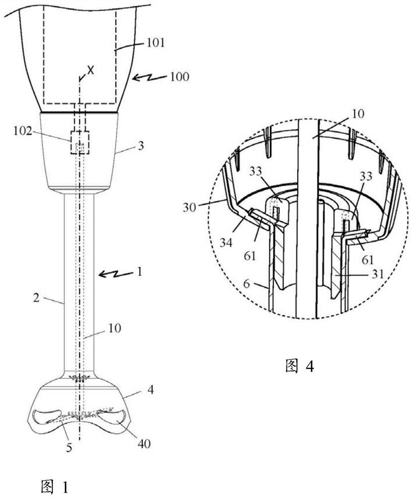
[0040] figure 1 A domestic blender is shown comprising a housing 100 containing a motor 101 schematically indicated by dashed lines and arranged along the longitudinal axis X of the housing, said motor 101 having an output shaft at Its lower end is equipped with a rotary driver 102 protruding to the outside of the housing 100 .

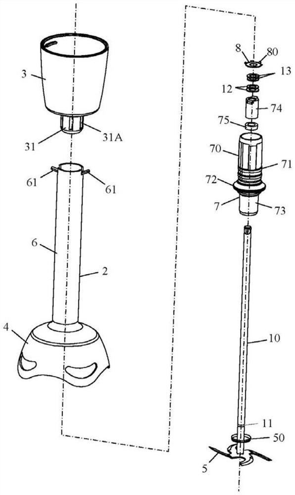
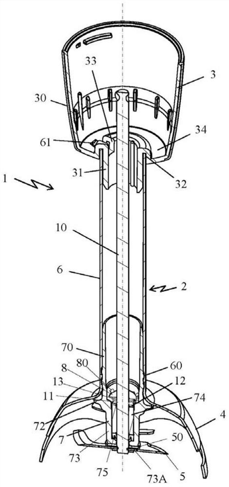
[0041] The household mixer comprises a stirring foot 1, and the stirring foot 1 comprises a tubular column body 2, and the tubular column body 2 comprises an upper end integrally co...


PUM


Abstract

The invention relates to a stirring foot (1), the stirring foot (1) comprises a column body (2), the column body (2) comprises a drive shaft (10), and the drive shaft (10) comprises an upper end and The lower end, the upper end is used to be driven to rotate by the electric housing, the lower end is connected to the outside of the column body (2), and the tool (5) is fixed on the lower end, the stirring foot ( 1) includes a connecting flange (3) that allows the detachable mounting of the stirring foot on the electric housing, and the stirring foot (1) includes a stop mechanism (8,11,13 ), the stop mechanism limits the axial rise of the drive shaft (10) inside the stirring foot (1), it is characterized in that the stop mechanism includes a stopper (8), and the stopper (8 ) comprises elastically deformable claws (80) in contact with the inner wall of said stirring foot (1), said claws ensuring the fixation of a stopper (8) in said stirring foot (1).

Description

technical field [0001] The present invention relates to the general technical field of household blenders of the elongated type, and more particularly to a blending foot for grinding ingredients immersed in a liquid. Background technique [0002] Such stirring feet are well known and frequently used. The stirring foot is often detachably connected to a housing containing a motor, and the stirring foot includes a stirring tool integrally connected to a shaft whose upper end is connected to the output shaft of the motor. Tools driven at high speed penetrate into the interior of the food to be prepared and cut, blend, emulsify, etc. [0003] A stirring foot disclosed in the known document CN202341837U, the stirring foot includes a shaft, the shaft includes a drive shaft, the drive shaft includes an upper end and a lower end, and the upper end is used to be driven by an electric housing Rotated, the lower end opens to the outside of the shaft and a tool is secured on the lower...

Claims


Application Information

Patent Timeline
Patent Type & Authority Patents(China)
IPC IPC(8): A47J43/07
CPCA47J43/0711A47J2043/04427
Inventor 弗兰克·阿姆兰斯特凡·格拉锡阿尔诺·维特尔
Owner SEB SA
Why Eureka
Try Eureka