Supercharge Your Innovation With Domain-Expert AI Agents!

Operating lever device

A technology for operating levers and buffer devices, applied in mechanical control devices, fluid pressure actuation devices, devices for preventing/limiting/restoring the movement of parts of a control mechanism, etc., can solve problems such as difficulties

Inactive Publication Date: 2009-12-09
KOMATSU LTD
View PDF4 Cites 0 Cited by
  • Summary
  • Abstract
  • Description
  • Claims
  • Application Information

AI Technical Summary

Problems solved by technology

However, in this case, the replacement work of the rotary damper must be performed after removing the operating lever, and the replacement work cannot be performed simply.
In addition, it is difficult to select the most suitable rotary damper for the operator from among a plurality of prepared rotary dampers.

Method used


Image

  • Operating lever device
  • Operating lever device
  • Operating lever device

Examples


Embodiment 1

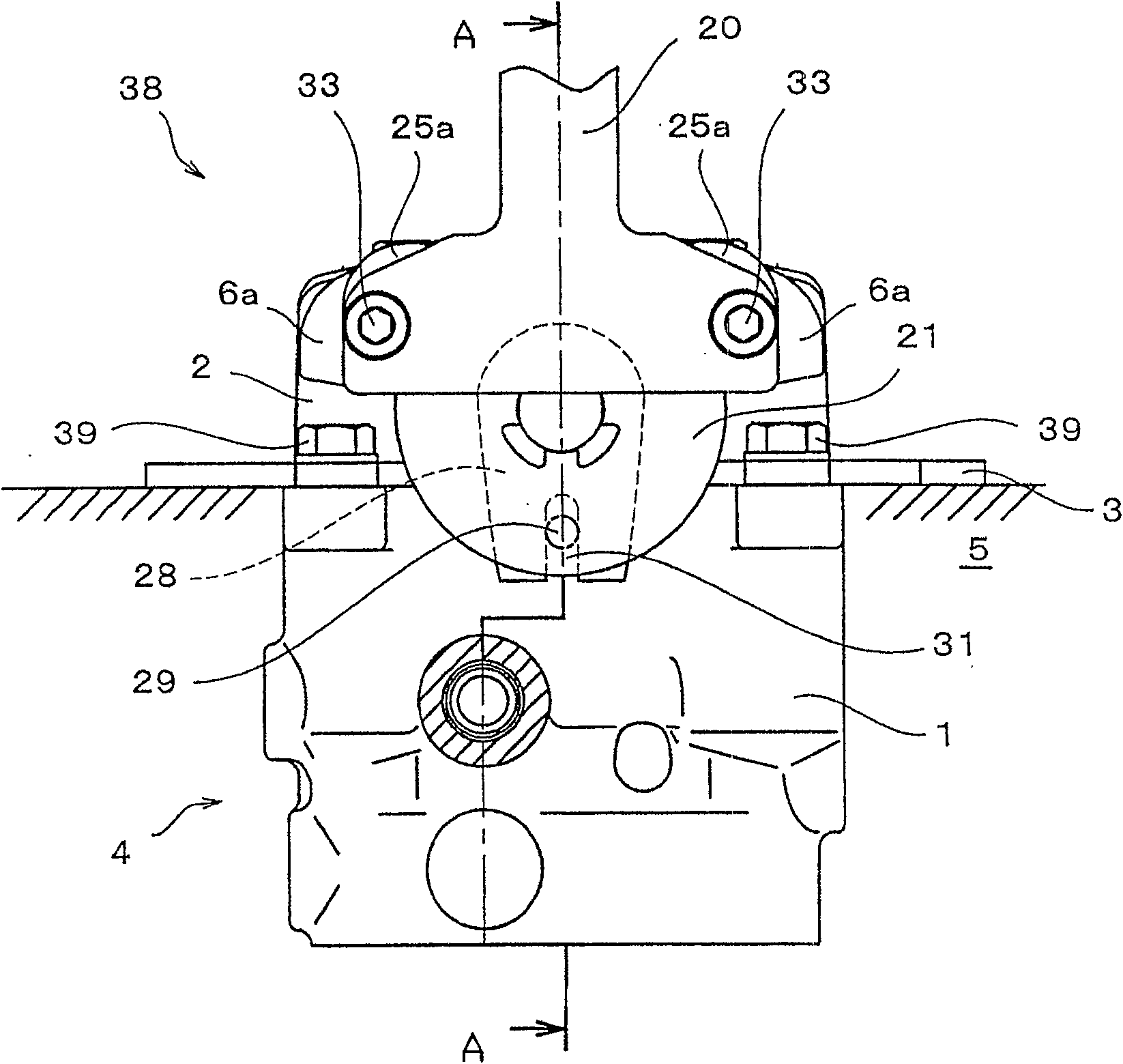
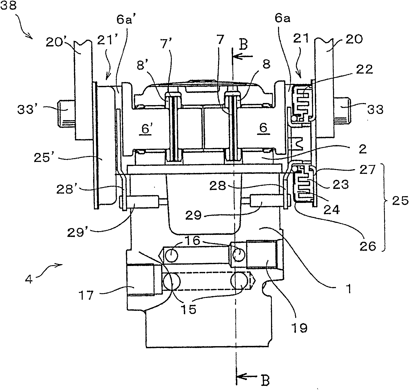
[0086] Such as figure 1 As shown, an operating lever device 38 is provided on the floor 5 of a cab or the like of a construction machine. The operating lever device 38 is fixed to the floor 5 with bolts 39 via the plate 3 . Such as figure 2 , Figure 4 As shown, the operating rod device 38 has: operating rods 20, 20' constituted by a pair of left and right groups; rotary damper devices 21, 21'; shafts 6, 6'; formed on the shafts 6, 6' The flange portions 6a, 6'a of the shaft and the shaft support body 2 which rotatably supports the shafts 6, 6', and the like. The shaft support body 2 is mounted on the main body 1 in which the valve body 4 is accommodated by fixing bolts 36 .

[0087] The operating levers 20, 20', the rotary damper devices 21, 21', the shafts 6, 6', and the flange portions 6a, 6'a are constituted by a pair of right and left pairs. The members of each group perform the same operation by tilting operation of the operating lever 20 or the operating lever 20...

Embodiment 2

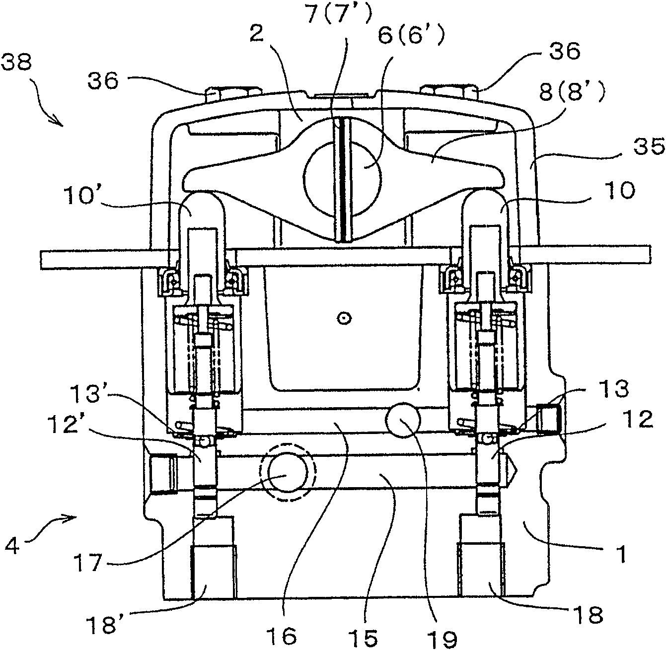
[0129] Figure 7 It is another embodiment 2 which shows the invention of this application. In the second embodiment, the configuration is the same as that of the first embodiment except that the fixing pin 29 is disposed above the shaft 6 . In addition, the operation as the operation lever device in the second embodiment can also play the same function as that of the operation lever device in the first embodiment. Therefore, in the description of the second embodiment, the same member symbols as those used in the first embodiment are used for the same structure as the first embodiment, and the description of the members is omitted. The following description focuses on the configuration different from that of the first embodiment.

[0130] Such as Figure 7 As shown, the fixing pins 29, 29' are disposed above the shafts 6, 6'. As the fixing pins 29, 29' are arranged above the shafts 6, 6', the long grooves of the damper rods 28, 28' are also arranged upward.

[0131] Accor...


PUM


Abstract

A rotor and a seat mounted on a first shell is disposed between an annular first shell and an annular second shell both constituting a damper case, thereby forming a rotary damper device. A damper lever on which the rotor is mounted is hooked on a fixing pin fixed to a body. Viscous fluid such as highly viscous oil is charged into a damper chamber formed between the rotor and the seat, and a viscous resistance is applied to the rotor and the seat. In a state in which a rotation center of the rotary damper device is deviated from a rotation center of the shaft which is rotated by the operating lever, the damper case is fixed to a flange portion of the shaft, the rotor and the seat are allowed to rotate relatively to each other by an inclining operation of the operating lever, and a resistance force from the rotary damper device is applied to the operating lever.

Description

technical field [0001] The present invention relates to a control lever device suitable for switching a directional switching valve or the like provided in a hydraulic circuit used in construction machines or industrial machines, for example. Background technique [0002] Generally, in construction machinery or industrial machinery, hydraulic motors are arranged on the left and right sides of the lower running body in addition to hydraulic cylinders for work, and are used as motors for traveling. These traveling electric motors control the traveling directional control valves to supply pressurized oil discharged from a hydraulic pressure source or to discharge the pressurized oil from the traveling electric motors. Accordingly, it is possible to control the traveling of the lower traveling body on the road. [0003] Also, in construction machinery or industrial machinery, a cabin (Japanese: キヤブ) for dividing the driver's cab is provided on the frame of the undercarriage, an...

Claims


Application Information

Patent Timeline
Patent Type & Authority Patents(China)
IPC IPC(8): G05G5/03G05G1/04F16F9/12E02F9/20F15B13/042F15B13/14F16F9/54
CPCG05G1/04F15B13/14F15B13/0422Y10T74/20582G05G5/03E02F9/2004
Inventor 本谷真芳堀秀司小塚大辅佐藤康广三宅功一
Owner KOMATSU LTD
Features
  • R&D
  • Intellectual Property
  • Life Sciences
  • Materials
  • Tech Scout
  • Unparalleled Data Quality
  • Higher Quality Content
  • 60% Fewer Hallucinations
Learn More