Roundness angle sorting and dividing plate

An angle subdivision and reticle technology, applied in measuring devices, instruments, optical devices, etc., can solve the problems of inability to measure the circular arc of the blade and low precision of the blade angle.

Inactive Publication Date: 2010-02-03
苏州市仁信精密量仪有限公司
View PDF5 Cites 0 Cited by
  • Summary
  • Abstract
  • Description
  • Claims
  • Application Information

AI Technical Summary

Problems solved by technology

[0006] The invention provides a roundness angle subdivision reticle, the purpose of which is to solve the problem that the existing reticle has low accuracy in measuring the angle of the blade and cannot measure the arc of the blade

Method used


Image

  • Roundness angle sorting and dividing plate
  • Roundness angle sorting and dividing plate

Examples


Embodiment 1

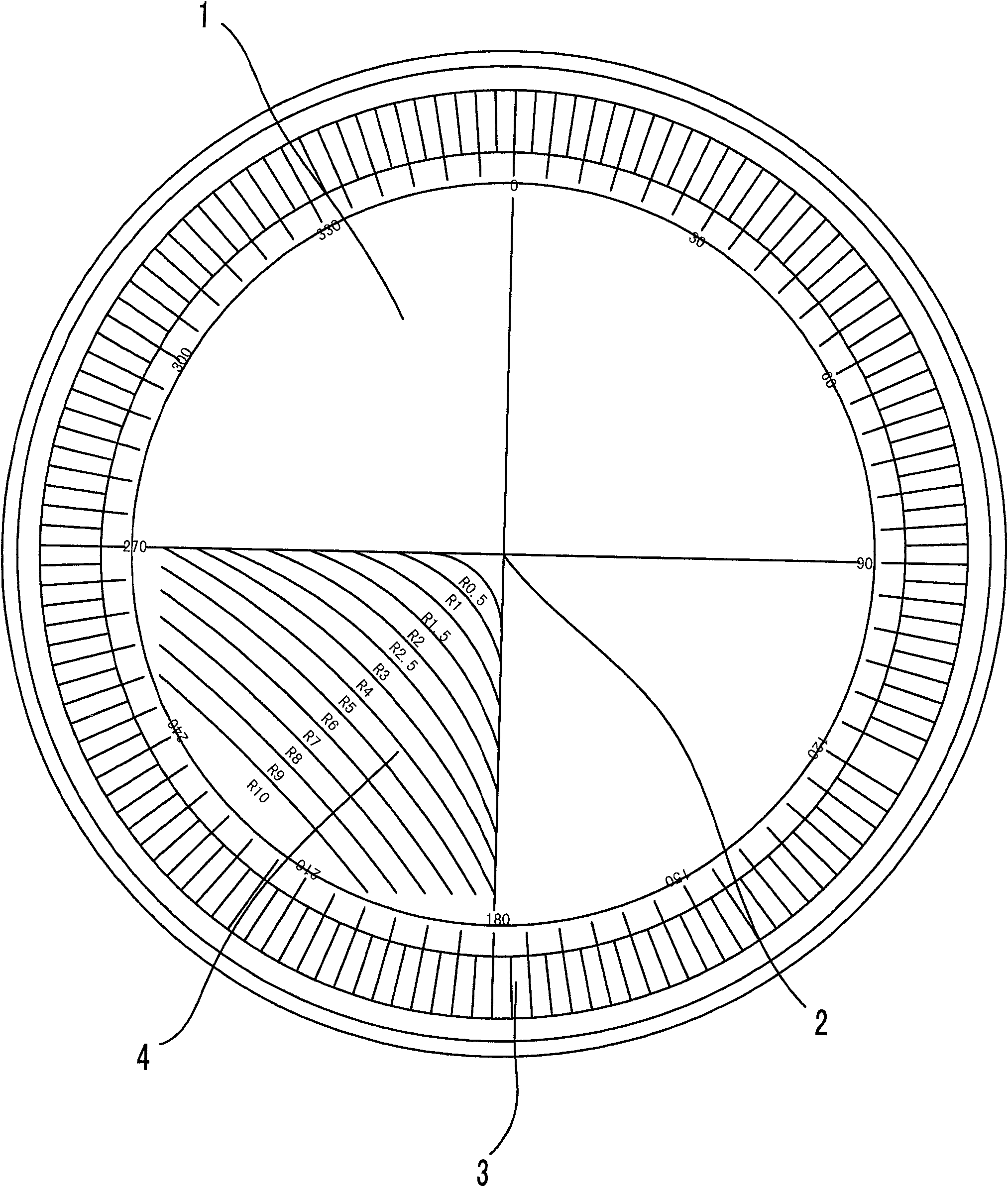
[0025] like figure 1 As shown, a roundness angle subdivision reticle includes a reticle body 1 and a cross line 2 engraved on the reticle body 1, and the reticle body 1 is also engraved with graduation lines and radians Graduation line, the graduation reticle is a set of graduation reticle 3 evenly distributed along the circumferential direction, the center of the graduation reticle coincides with the center of the cross line 2; The center of the line 2 is the center of the circle, and N graduation lines 3 are engraved within 360°, such as one graduation line 3 at intervals of 2°30′ within 360°, such as 0°, 2°30′, 5°0′ , 7°30′, ...... etc.

[0026] Described radian reticle is a group of radian reticle 4, and this radian reticle 4 is a group that is described outwardly from the center of cross line 2 in the third quadrant of reticle body 1 and the standard size series of cutter blade arc radius ( Such as R0.5, R1.0, R1.5, R2.0, R2.5, ... etc.) corresponding to the radian scal...

Embodiment 2

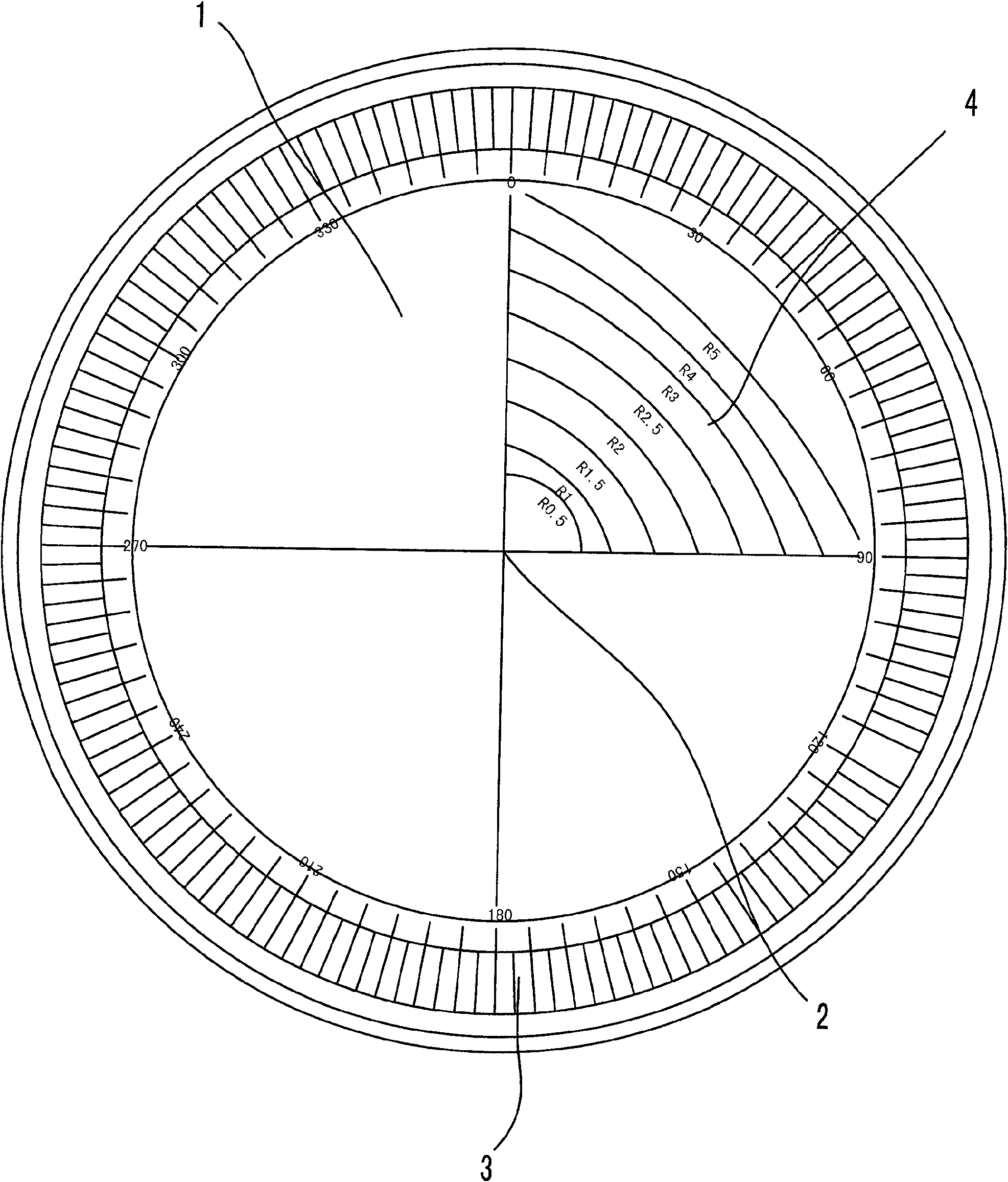
[0030] like figure 2 As shown, a roundness angle subdivision reticle is different from Embodiment 1 in that: the radian reticle 4 is a set of circle centers and cross lines drawn in any quadrant on the reticle body 1 Concentric radian reticles 4 with coincident centers, the concentric radian reticles 4 intersect the cross line in both horizontal and vertical directions, and the radius of the arc is consistent with the standard size of the arc radius of the tool blade. Other structures are the same as those in Embodiment 1, and will not be described in detail here.


PUM


Abstract

The invention discloses a refined radian and angle reticule, which comprises a reticule body and reference lines that are carved on the reticule body, and a group of index reading lines that are usedfor measuring the blade angles and a group of radian reading lines that are used for measuring the blade radians are arranged on the reticule; the index reading lines are angle reading lines that arearranged in a circumference direction with the center of the reticule as a circle center; the radian reading lines are the arc reading lines that are corresponding to the blade radians. The proposal of the refined radian and angle reticule solves the problem that existing reticules do not have high precision when measuring the blade angles and can not measure the blade radians.

Description

technical field [0001] The invention relates to an accessory used in an optical projection tool presetter, in particular to a roundness angle subdivision reticle. Background technique [0002] The optical projection tool presetter is mainly used to measure the coordinate position of the cutting edge of the tool used in CNC machine tools, machining centers and flexible manufacturing units, and can fully meet the requirements of high efficiency, high precision and repeatability of CNC machine tools and machining centers. In order not to take up valuable working time of the machine tool, it is necessary to use the tool presetter to perform precise detection and pre-adjustment of the tool outside the production line (off-line measurement), without having to repeatedly test the tool on the machine tool. The use of the reticle is inseparable from the precise detection and pre-adjustment of the tool. [0003] The reticle is an important part of the optical projection tool presette...

Claims


Application Information

Patent Timeline
Patent Type & Authority Patents(China)
IPC IPC(8): G01B11/24G01B11/26
Inventor 陆庆年
Owner 苏州市仁信精密量仪有限公司
Why Eureka
Try Eureka