Image forming apparatus
An image and surface-mounted technology, which is applied to the electrical recording process using charge graphics, equipment and instruments for the electrical recording process using charge graphics, and can solve problems such as temperature differences and heat that cannot be released
- Summary
- Abstract
- Description
- Claims
- Application Information
AI Technical Summary
Problems solved by technology
Method used
Image
Examples
no. 1 example
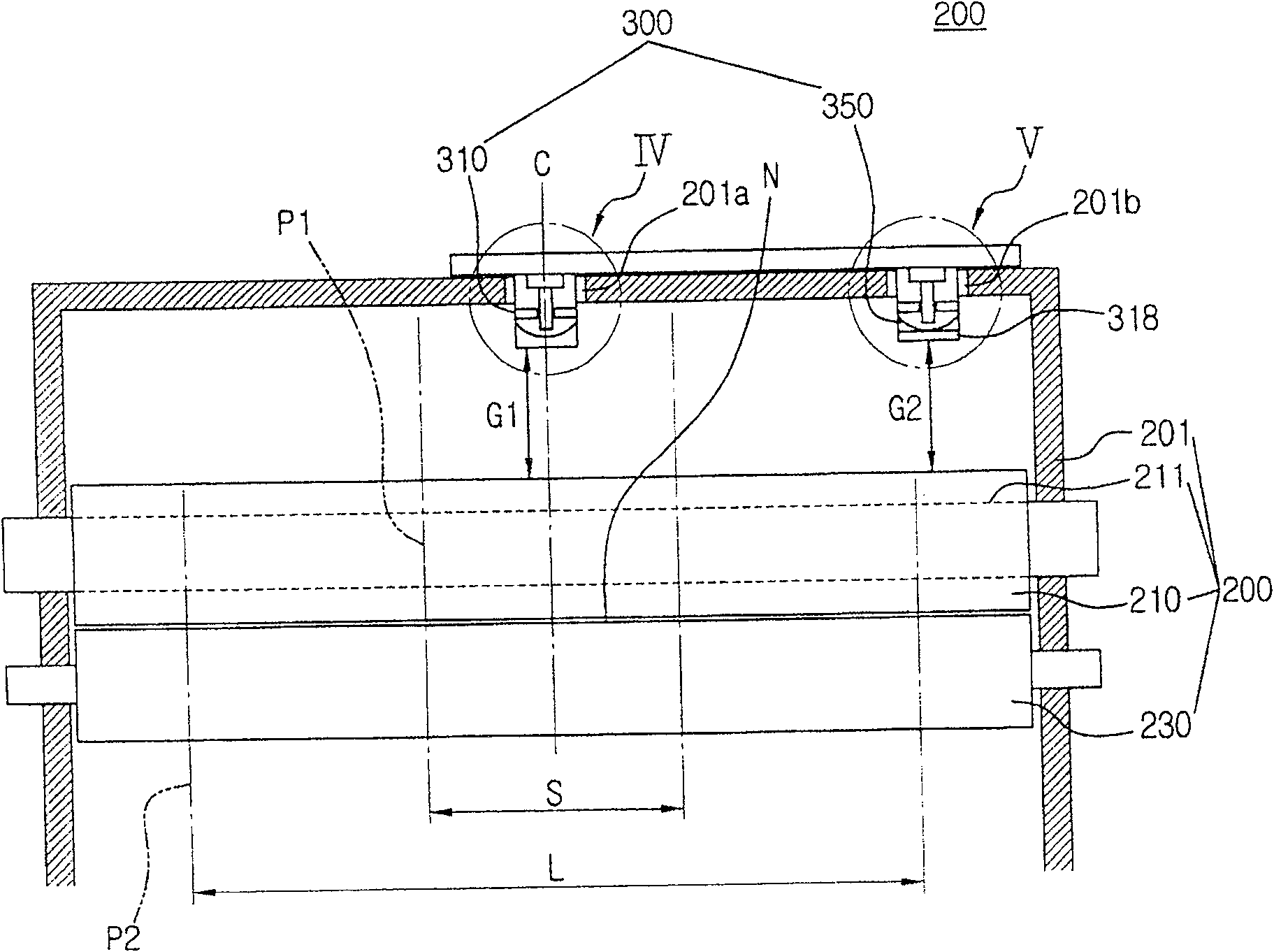
[0054] In the first embodiment, in order to cope with the temperature difference in the fixing nip, as image 3 As shown, the gap G1 between the inner thermostat 310 and the surface of the heating roller 210 can be set to be equal to the gap G2 between the outer thermostat 350 and the surface of the heating roller 210, and the response time of the inner thermostat 310 can be set to Different from the response time of the thermostat 30.
[0055] Here, an open type thermostat may be used for the inner thermostat 310 and a closed type thermostat may be used for the outer thermostat 350 in order to set different response times.
[0056] Figure 5A It is an enlarged view showing the structure of the open type internal thermostat shown in IV in the figure. Such as Figure 5A As shown, the open-type internal thermostat 310 includes a housing 311, a bimetal 312 installed in the housing 311 facing the surface of the heating roller 210, an operating pin 313 contacting the surface of ...
no. 2 example
[0060] Figure 7 is a schematic sectional view showing the structure of an image fixing device according to a second embodiment of the present invention. Figure 8A and 8B are shown for Figure 7 Enlarged view of the structure of the thermostat shown in VII and VIII.
[0061] refer to Figures 7 to 8B , to cope with the temperature difference in the fixing nip N, according to the image 3 In the same manner as the case shown in , the gap G1 between the inner thermostat 330 and the surface of the heating roller 210 is set equal to the gap G2 between the outer thermostat 370 and the surface of the heating roller 210, and the operating temperature of the inner thermostat 330 is set to Can be set to a different operating temperature than the thermostat 30 .
[0062] Here, the inner thermostat 330 and the outer thermostat 370 are Figure 6 Closed type thermostat shown in . some components with image 3 and 6 same as shown in . Therefore, the same elements are denoted by the...
no. 3 example
[0068] Figure 9 is a schematic sectional view showing the structure of an image fixing device according to a third embodiment of the present invention. refer to Figure 9 , the gap G3 between the inner thermostat 380 and the surface of the heating roller 210 can be set to be different from the gap G2 between the outer thermostat 390 and the surface of the heating roller 210, and the response time and the operating temperature of the inner thermostat 380 are set respectively Be the same as that of the external thermostat 390.
[0069] Here, the gap G3 is set narrower than the gap G2 so that the heat transferred from the heating roller 210 to the inner thermostat 380 is substantially equal to the heat transferred from the heating roller 210 to the outer thermostat 390 .
[0070] By using a closed thermostat for both the inner thermostat 380 and the outer thermostat 390 or an open thermostat for both the inner thermostat 380 and the outer thermostat 390, the response time of t...
PUM
 Abstract
Description
Claims
Application Information
 - R&D
- Intellectual Property
- Life Sciences
- Materials
- Tech Scout
- Unparalleled Data Quality
- Higher Quality Content
- 60% Fewer Hallucinations
Browse by: Latest US Patents, China's latest patents, Technical Efficacy Thesaurus, Application Domain, Technology Topic, Popular Technical Reports.
© 2025 PatSnap. All rights reserved.Legal|Privacy policy|Modern Slavery Act Transparency Statement|Sitemap|About US| Contact US: help@patsnap.com


