
Heating device using photodetector to detect temperature and protection method thereof

A photodetector and temperature detection technology, applied in fluid heaters, lighting and heating equipment, etc., can solve problems such as difficult heating devices, difficult space configuration, and easy damage

Active Publication Date: 2017-10-27
MPI CORP
View PDF1 Cites 0 Cited by
  • Summary
  • Abstract
  • Description
  • Claims
  • Application Information

AI Technical Summary

Problems solved by technology

However, in order to avoid the problem that the photodetector is easily damaged in a high temperature difference environment, in conventional applications, the photodetector is not arranged around the light source but receives light through a light guide element (such as a lens, a quartz tube, etc.), In order to allow the light emitted by the light source to be transmitted to the photodetector, the photodetector is opposite to the light source through the light guide element. Such a design is difficult to arrange in space in a small-sized device, so it is difficult to apply to the heating device.

Method used


Image

  • Heating device using photodetector to detect temperature and protection method thereof
  • Heating device using photodetector to detect temperature and protection method thereof
  • Heating device using photodetector to detect temperature and protection method thereof

Examples


Embodiment Construction

[0036] In order to describe the detailed structure, features, assembly or use of the present invention in detail, the following preferred embodiments are described below with accompanying drawings.

[0037] The applicant first explains here that in the embodiments and drawings to be described below, the same reference numerals denote the same or similar elements or structural features. Secondly, when it is mentioned that an element is arranged on another element, it means that the aforementioned element is directly arranged on the other element, or that the aforementioned element is indirectly arranged on the other element, that is, there is also an arrangement between the two elements. have one or more other elements.

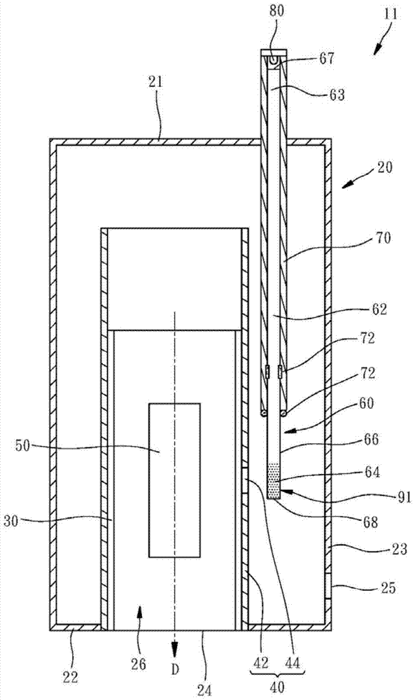
[0038] Such as figure 1 As shown, the heating device 11 provided by a first preferred embodiment of the present invention includes a housing 20, a transparent tube 30, an opaque tube 40, a heater 50, a light guiding rod 60, a protective tube 70, a light dete...


PUM


Abstract

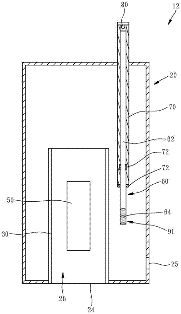
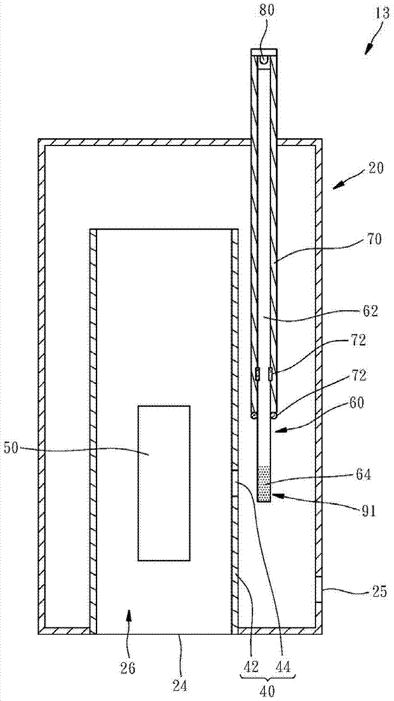
The invention relates to a heating device using a photodetector to detect temperature and its protection method. The heating device includes a casing with a flow channel inside, a heater arranged in the flow channel, a light guide rod, a light guide element and a light detector. The light guide rod has a transparent body, a first end and a second end located inside the casing, the light guide element is located at the second end and faces the heater, so as to direct the light emitted by the heater to the direction of the first end guide. The light detector is located at the first end and faces the second end, so as to indirectly receive the light irradiated by the heater on the light guide element through the transparent body. Therefore, the photodetector can be used to detect the temperature of the heater, and the heater can be effectively protected from overheating due to its fast response speed, and the photodetector can avoid the problem of being easily damaged due to the high temperature difference environment , and the heating device is quite flexible in spatial configuration.

Description

technical field [0001] The present invention relates to a heating device, in particular to a heating device using a photodetector to detect temperature and a protection method thereof. Background technique [0002] The conventional heating device mainly includes a housing with a flow channel inside, and a heater arranged in the flow channel, which is used for fluid (usually air) to enter from an inlet of the housing and pass through the flow channel. It is discharged from an outlet of the casing, and when the fluid passes through the heater, the temperature of the fluid is increased due to taking away the heat from the heater, so the heating device can heat the object located outside the outlet by discharging the high-temperature fluid. [0003] There is usually a temperature sensor outside the outlet of the heating device, such as thermocouple (thermocouple), bimetal thermostat (bimetal thermostat), etc., the temperature sensor is used to sense the temperature of the fluid ...

Claims


Application Information

Patent Timeline
Patent Type & Authority Patents(China)
IPC IPC(8): F24H9/20
Inventor 克里斯塔·赫尔格·雅各李岳颖张盈乔
Owner MPI CORP
Learn More