
Apparatus for orienting magnetic flakes

A technology of magnetic sheets and magnets, which is applied in the field of devices that obtain optical illusion effects, and can solve problems such as difficult realization of devices

Active Publication Date: 2007-07-25
VIAVI SOLUTIONS INC
View PDF16 Cites 50 Cited by
  • Summary
  • Abstract
  • Description
  • Claims
  • Application Information

AI Technical Summary

Problems solved by technology

Color shifting effects with optimal appearance, such as large color shifts and high chromaticity values, are difficult to achieve with the devices of EP1 493 590 when the particles providing the effect are parallel or nearly parallel to the substrate surface

Method used


Image

  • Apparatus for orienting magnetic flakes
  • Apparatus for orienting magnetic flakes
  • Apparatus for orienting magnetic flakes

Examples


Embodiment Construction

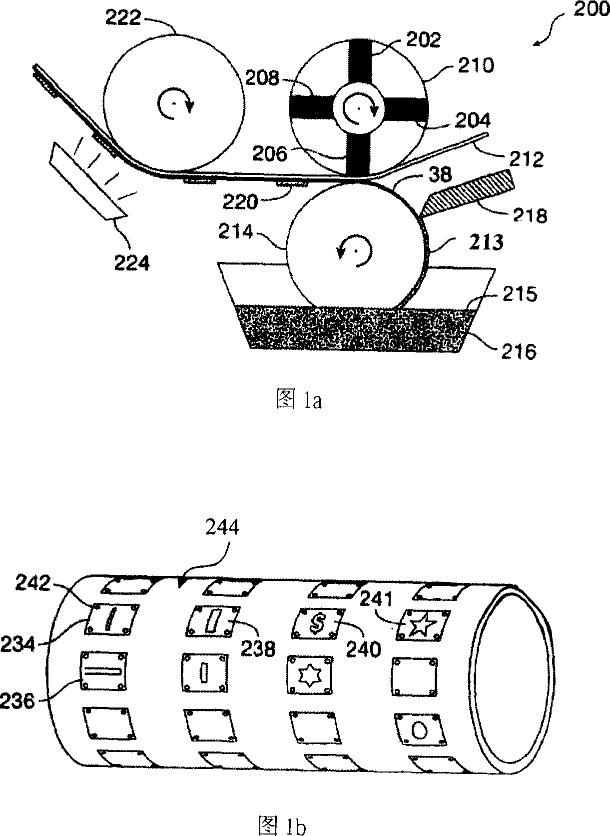
[0059] [58] A typical embodiment of the apparatus in the present invention will now be described: An apparatus for orienting magnetic flakes printed on a substrate in pigment, ink, or other fluid carrier in a continuous linear process, first referring to Fig. 1a- 1c.

[0060] [59] FIG. 1a is a simplified side view of a portion of a printing apparatus 200 according to an embodiment of the invention. An important part of the device of the invention is the magnetic roller, which can be understood here as a roller with magnetized and non-magnetized or differently magnetized parts. The term "magnetized portion" used herein in relation to a roll in the present invention means that a permanent magnet is implanted in the roll, or a selectively magnetized portion of the roll is adjacent to its surface, or another shaped portion of the roll has a different Predetermined magnetism of area magnetism to form a predetermined magnetic field profile emanating from the roll.

[0061] [60] In...


PUM


Abstract

The invention relates a printing apparatus including a magnetic rotatable roller with a smooth even outer surface for aligning magnetic flakes in a carrier, such as an ink vehicle or a paint vehicle to create optically variable images in a high-speed, linear printing operation. Images can provide security features on high-value documents, such as bank notes. Magnetic flakes in the ink are aligned using magnetic portions of the roller, that can be formed by permanent magnets embedded in a non-magnetic roller body, or selectively magnetized portions of a flexible magnetic cover of the roller. In some embodiments, the roller is assembled for a plurality of interchangeable sections, which can include spinning magnets. Selected orientation of the magnetic pigment flakes can achieve a variety of illusive optical effects that are useful for decorative or security applications.

Description

[0001] Cross References to Related Applications [0002] [01] The present invention claims the priority of Provisional Patent Application No. 601759,356 entitled "Magnetic Rollers For Alignment Of Dispersed Magnetic Particles And Patterned Optical Security Image Device With Illusion Of Depth" filed on January 17, 2006 and 2006 Priority to patent application number 11 / 552,219, filed October 24, entitled "Patterned Optical Structures with Enhanced Security Features." These applications are hereby incorporated by reference in their entirety. [0003] [02] This patent application is a partial continuation application of the application serial number 11 / 552,219 submitted on October 24, 2006; and the application serial number 11 / 552,219 is a patent submitted on December 20, 2005 Continuation-in-Part of Application Serial No. 11 / 313,165, filed December 22, 2004, Application Serial No. 11 / 022106, current publication number 2005 / 0106367 in the United States A continuation-in-part of a ...

Claims


Application Information

Patent Timeline
IPC IPC(8): B41M3/00B41F17/00B42D15/00B05D3/14B05D5/06
CPCB05D3/207B05D5/061B41F13/10B41F13/18B41M3/00B41M3/14G02B5/0808
Inventor 凡拉帝米尔·P.·瑞克沙杰伊·M·霍尔曼保罗·G·库姆斯查尔斯·T·迈肯特斯罗杰·W·菲利普
Owner VIAVI SOLUTIONS INC
Features
  • Generate Ideas
  • Intellectual Property
  • Life Sciences
  • Materials
  • Tech Scout
  • Unparalleled Data Quality
  • Higher Quality Content
  • 60% Fewer Hallucinations
Learn More