LED driving circuit with the temperature compensation

A technology for light-emitting diodes and driving circuits, which is applied in the directions of electroluminescent light sources, electric lamp circuit arrangements, light sources, etc., and can solve problems such as changes in the chromaticity and brightness of light-emitting diodes

Inactive Publication Date: 2007-08-01
SYST GEN
View PDF0 Cites 5 Cited by
  • Summary
  • Abstract
  • Description
  • Claims
  • Application Information

AI Technical Summary

Problems solved by technology

However, the disadvantage of the above circuit is that the chrom...

Method used


Image

  • LED driving circuit with the temperature compensation
  • LED driving circuit with the temperature compensation
  • LED driving circuit with the temperature compensation

Examples


Embodiment Construction

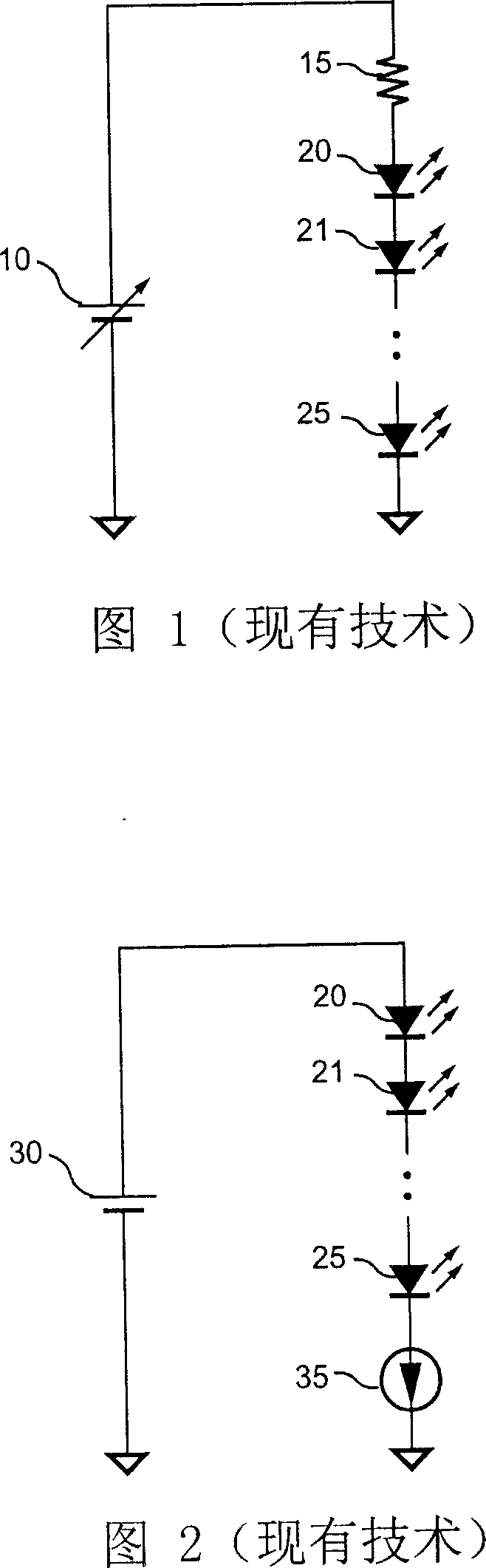
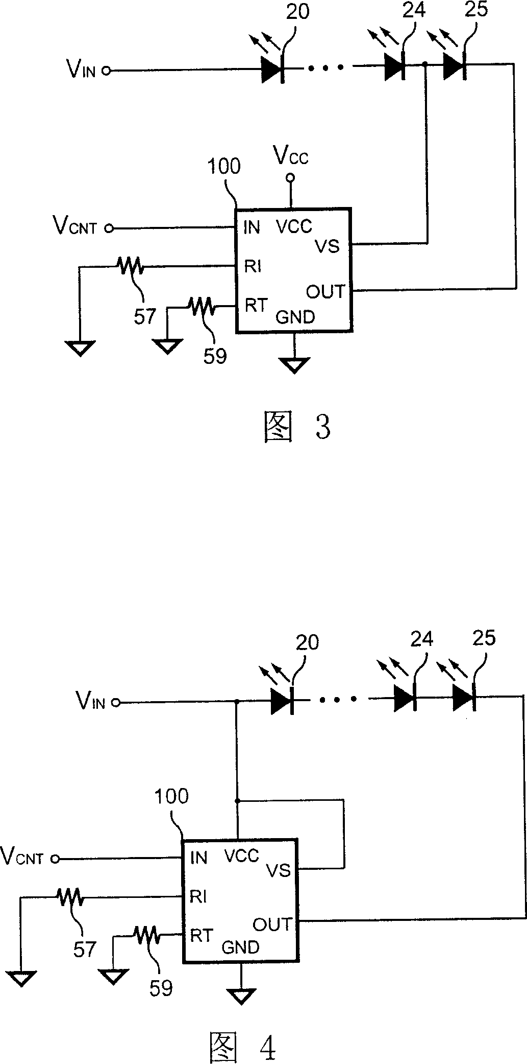
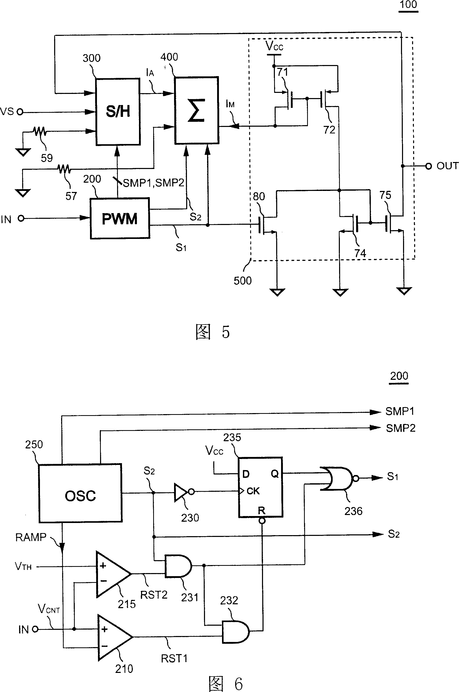
[0079] 3 and 4 are multiple embodiments of an LED driving circuit according to the present invention, wherein the LEDs 20-25 are connected in series. A voltage source V IN It is to supply the light-emitting diodes 20-25. A control circuit 100 is coupled to the LEDs 20-25. FIG. 3 shows that the control circuit 100 is powered by a voltage source VCC. FIG. 4 shows that the power of the control circuit 100 is directly provided by the voltage source VIN. An output terminal OUT of the control circuit 100 generates a LED current for controlling the LEDs 20 - 25 . A first resistor 57 is connected to the control circuit 100 for determining the current value of the LED current. A control terminal IN of the control circuit 100 is used to receive a control signal V CNT , to turn on / off the LED current, and determine the duty cycle of the LED current. A detection terminal VS of the control circuit 100 is connected to the LEDs 20 - 25 for detecting a voltage of the LEDs. The LED volt...


PUM


Abstract

The provided drive circuit for controlling LED luminance comprises a control circuit to generate current and detect LED voltage for adjusting its current, wherein the LED current is relative with LED temperature.

Description

technical field [0001] The present invention relates to an LED (Light Emitting Diode) driver, and more particularly, the present invention relates to a control circuit for controlling the LED driver. Background technique [0002] The LED driver can control the brightness of the LED according to its temperature characteristics. The LED driver is used to control the current value flowing through the LED. Although a higher current can enhance the brightness of the LED, it will reduce the service life of the LED. FIG. 1 shows a conventional LED driver circuit. The adjustable voltage power supply 10 provides the current I through a resistor 15 LED Give a plurality of light emitting diodes 20-25. Current I LED As follows: [0003] I LED = V - V F 20 - V ...

Claims


Application Information

Patent Timeline
IPC IPC(8): H05B33/08H05B37/02H05B44/00
Inventor 杨大勇
Owner SYST GEN
Why Eureka
Try Eureka