Solar energy control

A technology of solar energy and solar concentrators, which is applied in the field of solar energy systems and can solve problems such as damage

Inactive Publication Date: 2007-08-08
舍奇实验室-阳光氢能量公司
View PDF0 Cites 11 Cited by
  • Summary
  • Abstract
  • Description
  • Claims
  • Application Information

AI Technical Summary

Problems solved by technology

Such plates are made of refractory materials to withstand the substantial heat of the sun's beams, and these materials are rather brittle and easily damaged by the influence of the external environment

Method used


Image

  • Solar energy control
  • Solar energy control
  • Solar energy control

Examples


Embodiment Construction

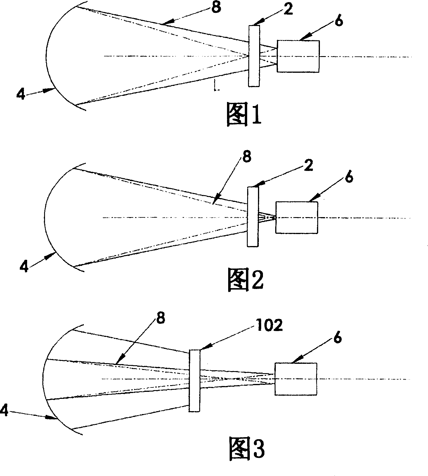
[0026] Figure 1 schematically shows a shading device 2 according to the invention arranged between a solar concentrator shown as a curved mirror 4 and a solar receiver 6 such as is known in the prior art. The curved mirror 4 focuses the sun's rays into a cone-shaped solar beam 8 , while the solar receiver 6 is positioned approximately at the apex of this cone to receive the solar beam 8 . The heat generated in the solar receiver 6 by the sun beam 8 is utilized in various ways as is known in the art.

[0027] In FIG. 1 the shading device 2 is shown in an open position in which all sun beams pass through the shading device and are received by the solar receiver 6 . FIG. 2 schematically illustrates the operation of an embodiment of a shading device 2 utilizing a plurality of movable shading panels to block the sun beam 8 and prevent varying parts of the sun beam 8 from reaching the solar receiver 6 . FIG. 2 shows the shading device 2 in a partially closed position, with only a p...


PUM


Abstract

A solar energy collection system includes a solar concentrator operative to direct a concentrated solar beam onto a solar receptor. A shutter plate is positioned between the solar concentrator and the solar receptor and is movable from an open position adjacent to the solar beam, to a closed position wherein at least a portion of the solar beam contacts a front face of the shutter plate and is blocked from contacting the receptor. A cooling circuit is operative to circulate a cooling fluid to remove heat from the shutter plate. A shutter drive is operative to move the at least one shutter plate from the open position to the closed position, and a shutter control is operative to stop movement of the shutter plate at a plurality of locations between the open position and the closed position.

Description

technical field [0001] The present invention relates to the field of solar energy systems and in particular to the control of energy received by solar receivers such as boilers, stoves and the like. Background technique [0002] Considerable progress is taking place in attempts to harness solar energy effectively and efficiently. A typical system includes curved mirrors shaped to collect and focus the sun's rays into a conically focused solar beam. A solar receiver is placed at the apex of the cone so that considerable heat can be generated in the receiver to perform the desired function requiring thermal energy. Curved mirrors typically consist of a set of smaller flat mirrors arranged on a curved frame to achieve the focusing effect, and curved mirrors can be quite large, depending on the power requirements of the receiver. [0003] Such solar systems are typically located in arid locations where the sun is reliably available, so that the heat generated by the sun's beam...

Claims


Application Information

Patent Timeline
Patent Type & Authority Applications(China)
IPC IPC(8): F24J2/40F24J2/46F24S23/70F24S23/71H02S40/22
CPCY02E10/40F24J2/4609F24J2/407Y02E10/41F24J2/07G02B17/0684G02B5/005G02B19/0042G02B19/0076G02B19/0023F24J2/40F24S40/10F24S50/80F24S20/20F24S50/00Y02E10/52
Inventor 莫里斯·J·图奇尔特
Owner 舍奇实验室-阳光氢能量公司
Why Eureka
Try Eureka