Wing structure for bionic aircraft

A technology of bionic aircraft and wings, which is applied in the field of bionic aircraft, can solve the problems of laborious flying and low flying efficiency, and achieve the effect of improving efficiency

Inactive Publication Date: 2007-08-15
苏小明
View PDF0 Cites 18 Cited by
  • Summary
  • Abstract
  • Description
  • Claims
  • Application Information

AI Technical Summary

Problems solved by technology

[0002] The wings of the existing bionic aircraft have an integral structure, and the wings flap back and forth during flight. When it is necessary to obtain upward force, the wings flap downward, and with the help of the reaction force of the air on the wings, the aircraft obtains upward force, but the wings return to the original position. When the wings are lifted up, they are subjected to the same amount of downward resistance from the air. As a result, the flying efficiency is very low and the flight is very laborious.

Method used


Image

  • Wing structure for bionic aircraft
  • Wing structure for bionic aircraft

Examples


Embodiment Construction

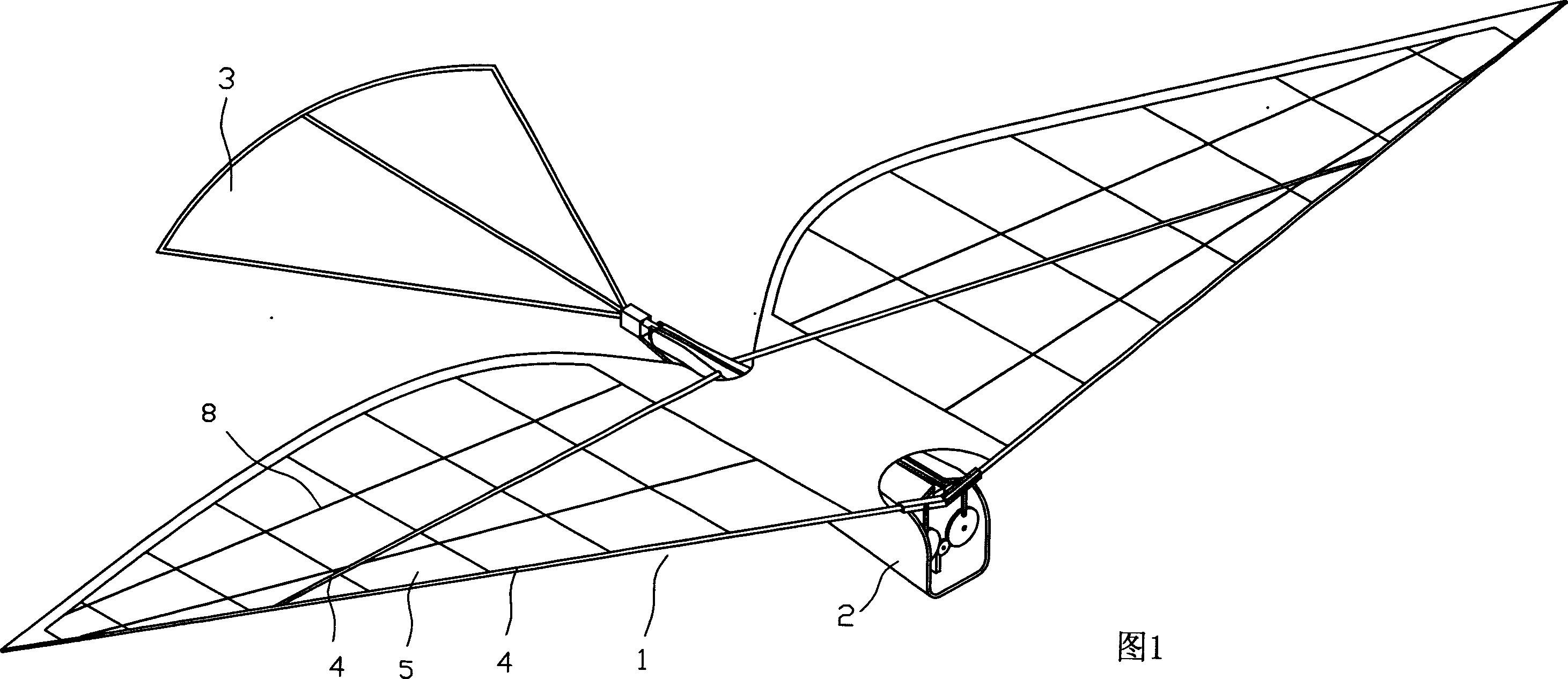
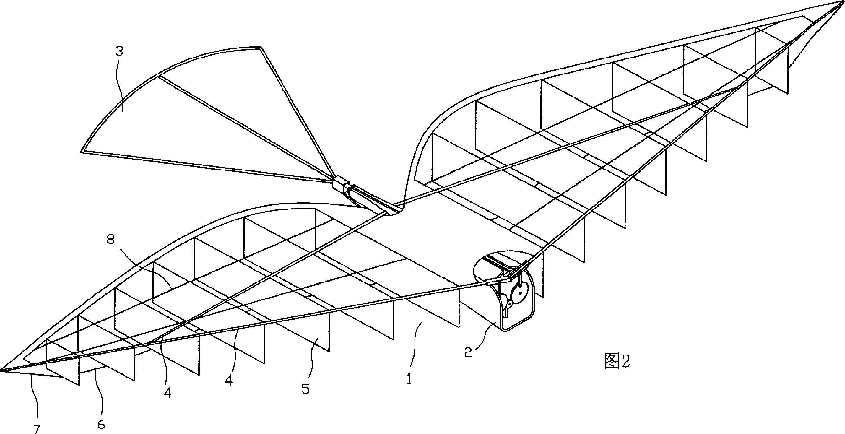
[0008] As can be seen from Figs. 1 and 2, the present invention comprises empennage 3, main body 2 and mechanism device installed in main body 2 and power supply or fuel tank, engine, servo for controlling empennage swing up and down, servo for controlling empennage rotation, circuit board, wings 1 is set on both sides of the top of the main body, and the mechanical device set in the main body 2 drives the wings 1 to reciprocate and vibrate, and uses the reaction force of the air to the wings to fly. Its characteristics are: the wings 1 are controlled by the skeleton 4, the movable wing surface 5, The connecting rod 6, the control stay wire 7, and the fixed retaining rod 8 are composed of one side of the movable wing surface 5 of the wing 1 fixed on the skeleton 4, and the movable wing surface 5 can rotate around this side as the axis center, and the control connecting rod 6 is arranged on the movable One side of the wing surface 5, and the movable wing surface 5 is connected i...


PUM


Abstract

The invention relates to a wing structure of bionic aircraft, characterized in that the wing is formed by a skeleton, movables fin, a control connecting rod, a control line, and a fixed baffle rod, wherein one edge of the movable fin is fixed on the skeleton to rotate around the edge, the control connecting rod is at one side of the movable fine to serially connect the movable fins, the control line connects the skeleton and the control connecting rod, and the fixed baffle rod is fixed with the skeleton. The inventive wing is formed by several movable fins, therefore, when lifts up, and wings moves downwards, the fins are integral to fly via counter force of air, and when fins return, the movable fins can change position to sag the movable fins, to improve the flying efficiency.

Description

technical field [0001] The invention relates to a bionic aircraft, in particular to a novel wing structure of the bionic aircraft. Background technique [0002] The wings of the existing bionic aircraft have an integral structure, and the wings flap back and forth during flight. When it is necessary to obtain upward force, the wings flap downward, and with the help of the reaction force of the air on the wings, the aircraft obtains upward force, but the wings return to the original position. When the wings are lifted up, they are subjected to the same amount of downward resistance of the air. As a result, the flying efficiency is very low and the flight is very laborious. Contents of the invention [0003] The purpose of the present invention is to improve and innovate on the shortcomings and deficiencies in the background technology, and to provide a novel wing structure of a bionic aircraft that can improve flight efficiency. [0004] The technical solution of the prese...

Claims


Application Information

Patent Timeline
Patent Type & Authority Applications(China)
IPC IPC(8): B64C33/02A63H27/28
Inventor 苏小明
Owner 苏小明
Why Eureka
Try Eureka