Eureka AIR delivers breakthrough ideas for toughest innovation challenges, trusted by R&D personnel around the world.

Magnetic floating driven motor

An actuation and motor technology, which is applied in the structural field of using a magnetizable component as a motor actuation shaft, can solve the problems of complex assembly of the combined component, high cost, and large volume of the voice coil motor.

Inactive Publication Date: 2007-08-15
TDK TAIWAN
View PDF0 Cites 1 Cited by
  • Summary
  • Abstract
  • Description
  • Claims
  • Application Information

AI Technical Summary

Problems solved by technology

[0004] The volume of the conventional voice coil motor is relatively large, and the assembly is more complicated due to more components, and the cost is also higher. Moreover, the actuation of the voice coil motor is to pass current through the coil, so it consumes a lot of power. This is like a camera. For small devices such as mobile phones that use batteries, this is a very difficult problem to overcome

Method used


Image

  • Magnetic floating driven motor
  • Magnetic floating driven motor
  • Magnetic floating driven motor

Examples


Embodiment Construction

[0025] In order to further understand the technology, means and effects that the present invention takes to achieve the predetermined purpose, please refer to the following detailed description and accompanying drawings of the present invention, and believe that the purpose, characteristics and characteristics of the present invention can be obtained from this in depth and For specific understanding, however, the accompanying drawings are only for reference and illustration, and are not intended to limit the present invention.

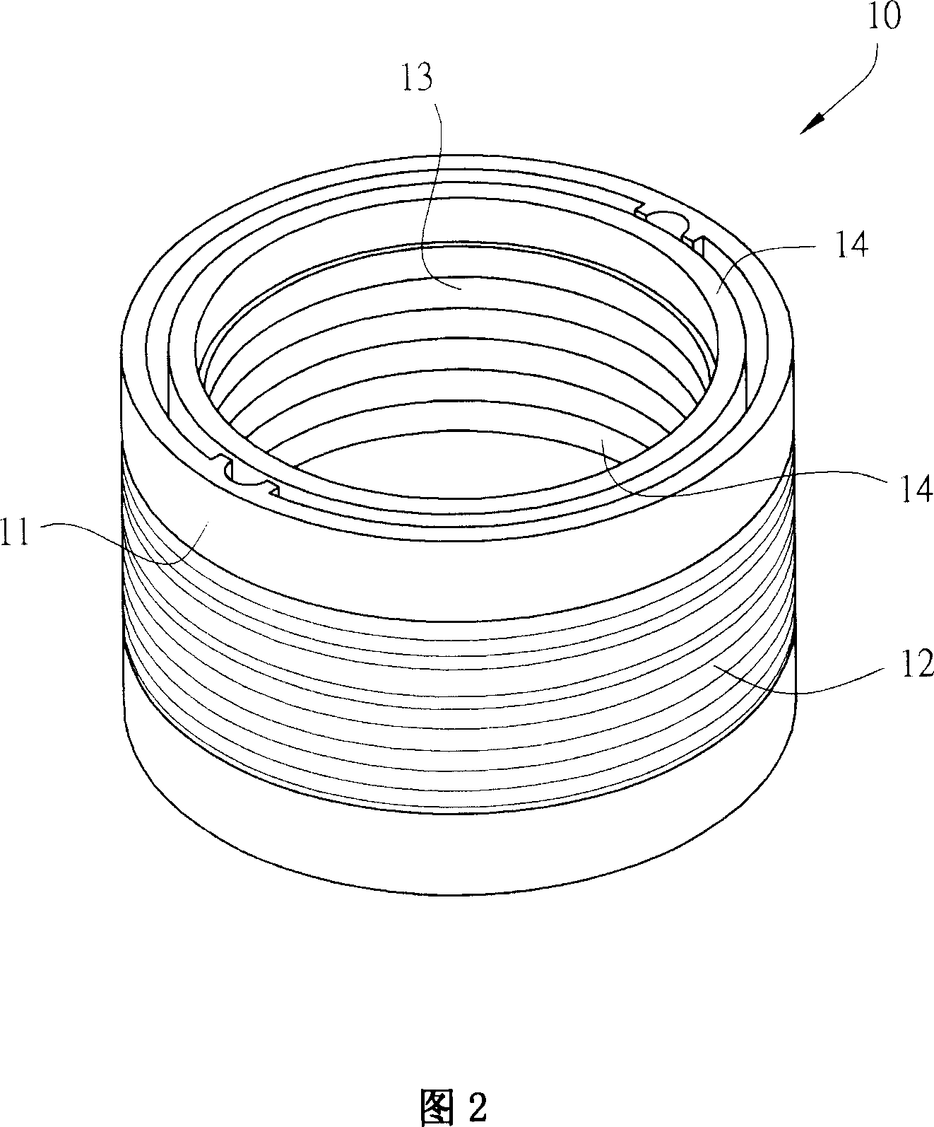
[0026] Please refer to FIG. 2, which is a three-dimensional schematic view of the magnetic levitation actuator motor of the present invention. FIG. 3 is an exploded perspective view of the magnetic levitation actuator motor of the present invention. It is a cylindrical shape with a hollow center, and a coil 12 can be wound around it. A magnetizable actuator 13 is placed in the central hollow of the base 11 and can move up and down. The magnetizable actu...


PUM


Abstract

The magnetic-levitation actuated motor comprises: a hollow base with a coil outside, at least one magnetic assembly embedded on the free end in hollow base, and a magnetisable actuated member put in the base hollow part fit to up-and-down moving. Wherein, the actuated member has the residual magnetic field intensity after magnetization; when electrifying the coil to generate magnetic flux and then magnetizes the actuator, the latter interacts with the assembly and holds a equilibrium point position after switching off current. This invention is simple and low cost for intermittent supplying power and saving energy.

Description

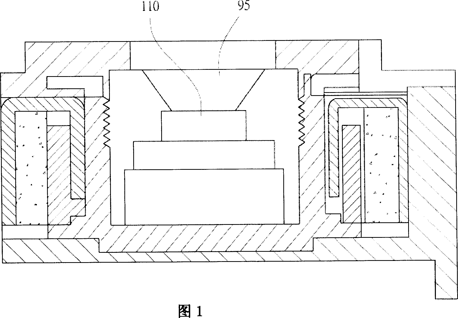
technical field [0001] The invention relates to a magnetic levitation actuating motor, in particular to a structure using a magnetizable component as the motor actuating shaft, which has the characteristics of power saving, few components and simple structure. Background technique [0002] In small consumer products such as mobile phones and digital cameras, small voice coil motors (VCMs) are often used as short-distance actuation motors. They have the advantages of small size and low price, and are suitable for actuating vertical displacement of magnetic heads / optical read-write heads. actuator, camera auto focus (Auto focus) actuator or camera lens telescopic field distance (Zoom) actuator...etc. [0003] Please refer to FIG. 1 , which is a schematic side view sectional view of a voice coil motor (VCM) with an automatic focus of a traditional camera. The axis of the traditional voice coil motor 100 is provided with an actuating part 110 that can place the lens 95. The actu...

Claims


Application Information

Patent Timeline
IPC IPC(8): H02K41/02G03B13/34
Inventor 张文嘉
Owner TDK TAIWAN
Why Eureka
Eureka Blog
Learn More