Supercharge Your Innovation With Domain-Expert AI Agents!

Cold-cathode tube drive device

A cold-cathode tube and driving device technology, applied in lighting devices, light sources, electrical components, etc., can solve the problems of reduced brightness, increased parasitic capacitance, and reduced lamp power efficiency

Inactive Publication Date: 2007-08-15
SUMIDA CORP
View PDF1 Cites 1 Cited by
  • Summary
  • Abstract
  • Description
  • Claims
  • Application Information

AI Technical Summary

Problems solved by technology

[0007] On the other hand, in the wide-screen and large-scale liquid crystal display panels developed in recent years, the electric wires 106a and 106b become longer due to the use of the long cold-cathode tube 103, etc. , if one of the two wires 106a, 106b connected to the two poles of the cold cathode tube 103 is wound to the other, the parasitic capacitance will increase, the leakage current will increase, and the brightness will decrease. Reduced efficiency

Method used


Image

  • Cold-cathode tube drive device
  • Cold-cathode tube drive device
  • Cold-cathode tube drive device

Examples


Embodiment Construction

[0039] Hereinafter, embodiments of the present invention will be described based on the drawings.

[0040] Implementation form one

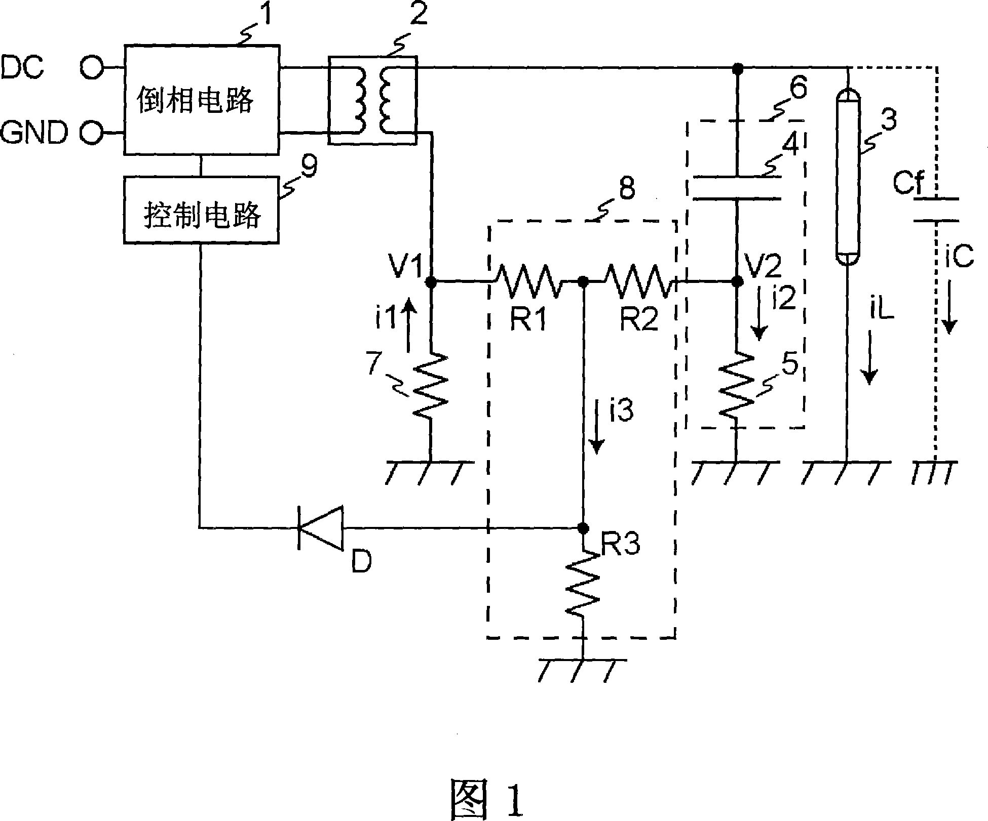
[0041] FIG. 1 is a circuit diagram showing the configuration of a cold cathode tube driving device according to Embodiment 1 of the present invention. In FIG. 1, the inverter circuit 1 is a circuit that is connected to a DC power supply and generates a high-frequency voltage. In addition, the step-up transformer 2 is a transformer that steps up the high-frequency voltage generated by the inverter circuit 1.

[0042] In addition, the cold cathode tube 3 is a cold cathode tube (CCFL) having one end connected to one end of the secondary winding of the step-up transformer 2 and the other end connected to a nearby ground wire (ground wire, a structure that becomes a ground wire, etc.). The cold cathode tube 3 is a discharge tube, and is a light-emitting tube that emits fluorescence when electrons moving between two electrodes collide with a sealing gas or...


PUM


Abstract

A cold-cathode tube drive device includes an inverter circuit (1) for generating a high-frequency voltage, a booster transformer (2) for boosting the high-frequency voltage generated by the inverter circuit (1), a cold-cathode tube (3) which is turned on by the high-frequency voltage after boosted by the booster transformer (2), a series circuit (6) having a reactance element (4) connected in parallel to the cold-cathode tube (3), a synthesis circuit (8) for combining the connected current value i2 of the series circuit (6) with the secondary side current value iL of the booster transformer (2) so as to indirectly detect the lamp current value iL of the cold-cathode tube (3), and a control circuit (9) for controlling the inverter circuit (1) according to the lamp current value iL indirectly detected by the synthesis circuit (8) and controlling the lamp current of the cold-cathode tube (3).

Description

Technical field [0001] The invention relates to a cold cathode tube driving device. Background technique [0002] In the prior art, in the backlight of liquid crystal display panels such as liquid crystal television receivers (hereinafter referred to as "liquid crystal TVs") and liquid crystal monitors, multiple cold cathode tubes (CCFL: Cold Cathode Fluorescent Tubes) are used. Lamp) (for example, refer to Patent Document 1). [0003] Fig. 4 is a circuit diagram showing a cold-cathode tube driving device in the prior art. In the device shown in FIG. 4, the inverter circuit 101 generates a high-frequency voltage, and the step-up transformer 102 boosts the high-frequency voltage generated by the inverter circuit 101, and applies the boosted high-frequency voltage to the cold cathode tube 103. The resonance capacitor 104 is a capacitor that forms a resonance circuit together with the secondary winding of the step-up transformer 102. [0004] The inverter circuit 101 obtains the att...

Claims


Application Information

Patent Timeline
IPC IPC(8): H05B41/24H05B41/392
CPCH05B41/2858H05B41/282H05B41/3925Y02B20/183Y02B20/00H05B41/24H05B41/288
Inventor 宫崎弘行
Owner SUMIDA CORP
Features
  • R&D
  • Intellectual Property
  • Life Sciences
  • Materials
  • Tech Scout
  • Unparalleled Data Quality
  • Higher Quality Content
  • 60% Fewer Hallucinations
Learn More