Three-way flow guide valve

A diverter valve and three-way technology, which is applied to multi-way valves, valve devices, engine components, etc., can solve the problems of high manufacturing and use costs, narrow application range, and difficulty in general use, and achieve the effect of convenient use and simple structure.

Inactive Publication Date: 2007-08-22
律天龙
View PDF0 Cites 8 Cited by
  • Summary
  • Abstract
  • Description
  • Claims
  • Application Information

AI Technical Summary

Problems solved by technology

[0002] In the prior art, there are many kinds of three-way diversion valves for conveying gas or liquid, but most of the three-way valves are designed for certain specific needs, and their scope of application is narrow and difficult to use universally. Some valve bodies In order to meet the needs of use, the structure is more complicated, and the manufacturing and use costs are higher

Method used


Image

  • Three-way flow guide valve

Examples


Embodiment 1

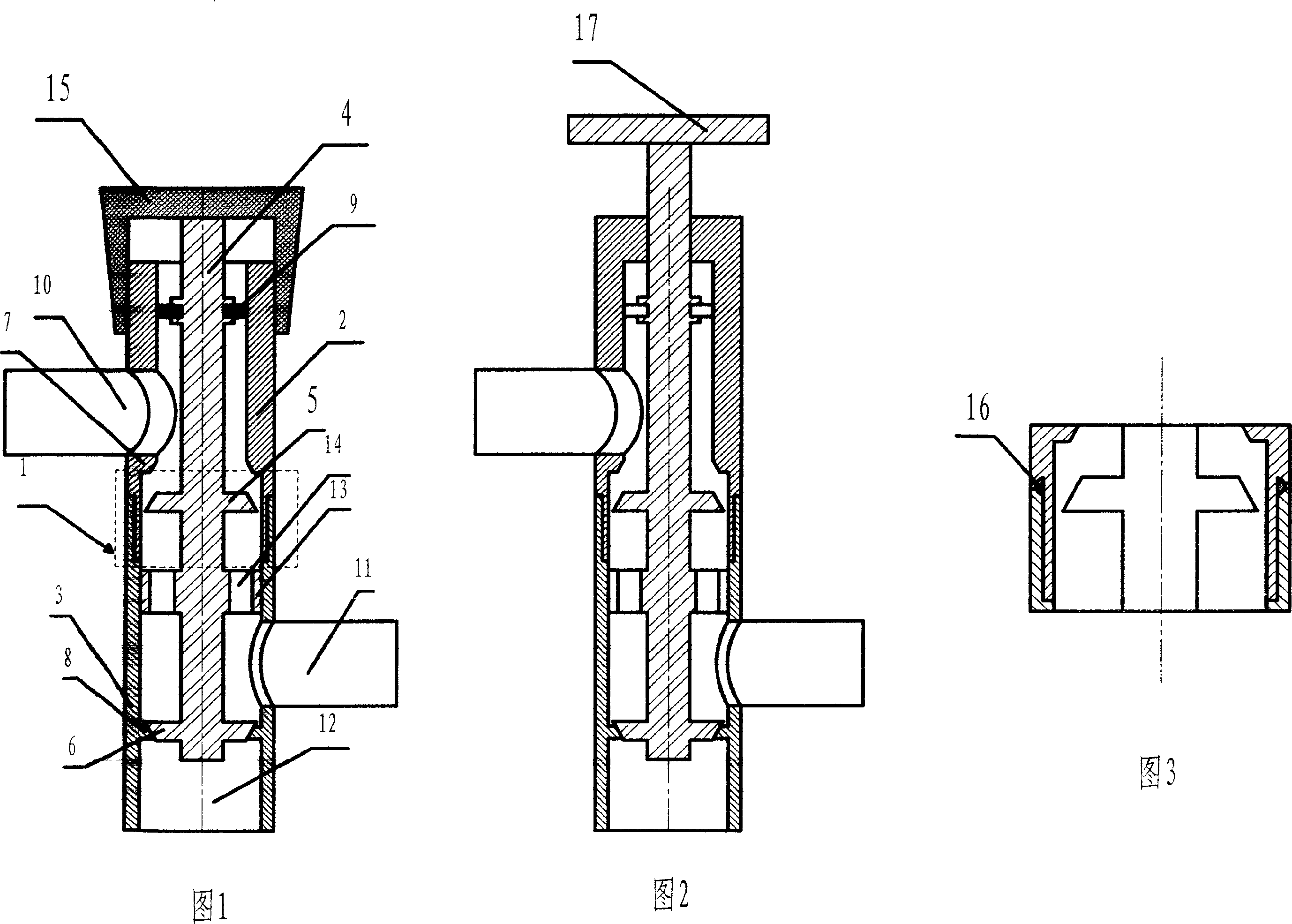
[0015] As shown in Figure 1, the present invention includes a valve body 1 with a tubular inner cavity. The valve body 1 is formed by screwing the upper valve body 2 and the lower valve body 3. The inner cavity of the valve body 1 is provided with a valve body that can slide up and down. The spool 4 is provided with two upper and lower bosses 5,6 on the spool 4, and two conical steps 7 are arranged on the two bosses 5,6 corresponding to the spool 4 in the upper valve body 2 and the lower valve body 3 respectively. , 8, the upper part of the valve core 4 and the inner chamber of the valve body 1 are provided with a sealing ring 9 for sealing, and the valve body 1 is respectively provided with an upper guide hole 10 and two conical steps between the sealing ring 9 and the upper conical step 5 There is a middle guide hole 11 between the steps, a lower guide hole 12 is opened under the lower conical step 6, and a guide flange 13 adapted to the inner cavity of the valve core is also...

Embodiment 2

[0018] As shown in FIG. 2 , the difference between embodiment 2 and embodiment 1 is that the valve core 4 protrudes from the upper end of the valve body 1 and connects with a runner 17 , and the valve core 4 and valve body 1 are connected by threads. Embodiment 2 is suitable for use when the flow rate is relatively large.


PUM


Abstract

The present invention discloses three-way flow-guiding valve. It includes a valve body with tubular inner cavity. The above-mentioned valve body is formed from upper and lower two portions which are screw-combined together, in the inner cavity of said valve body is set a valve core which can be upwards and downwards moved, on the valve core are set upper and lower two conical projections, and in the upper valve body interior and in the lower valve body interior two conical steps which are correspondent to said two conical projections of valve core are respectively set, between the upper part of valve core and inner cavity of valve body a sealing ring is set, on the valve body, between the sealing ring and upper conical step an upper flow-guiding hole is cut, between two conical steps a middle flow-guiding hole is cut and in the lower portion of lower conical step a lower flow-guiding hole is cut, on the valve core also is set a guide flange adaptable to the inner cavity of valve body, on the described guide flange a through hole is cut.

Description

technical field [0001] The invention relates to a three-way diversion valve for conveying gas or liquid. Background technique [0002] In the prior art, there are many kinds of three-way diversion valves for conveying gas or liquid, but most of the three-way valves are designed for certain specific needs, and their scope of application is narrow and difficult to use universally. Some valve bodies In order to meet the needs of use, the structure is relatively complicated, and the manufacturing and use costs are relatively high. Contents of the invention [0003] The purpose of the present invention is to provide a three-way diversion valve with simple structure and good versatility. [0004] Its technical solution is as follows: [0005] Three-way diversion valve, which includes a valve body with a tubular inner cavity, the above-mentioned valve body is composed of upper and lower sections screwed together, a valve core that can slide up and down is arranged in the inner ...

Claims


Application Information

Patent Timeline
Patent Type & Authority Applications(China)
IPC IPC(8): F16K11/044
Inventor 律天龙律北平
Owner 律天龙
Why Eureka
Try Eureka