Intelligent controll vortex street flow sensor

A vortex flow and sensor technology, which is applied in the field of fluid control devices and instrumentation pipeline fluid control devices, can solve the problems of not being able to measure the flow well, and inconvenient to connect or cut off, and achieve the effect of high precision.

Active Publication Date: 2009-08-26
NANJING XIAO INSTR MEASUREMENT
View PDF4 Cites 0 Cited by
  • Summary
  • Abstract
  • Description
  • Claims
  • Application Information

AI Technical Summary

Problems solved by technology

However, in the past, these control devices have the following defects in use, that is, they cannot measure the flow of fluid flowing through the pipeline well, or they cannot help the supply unit to control the amount of fluid for charging management.
It is also very inconvenient to control its on or off at the same time

Method used


Image

  • Intelligent controll vortex street flow sensor

Examples


Embodiment Construction

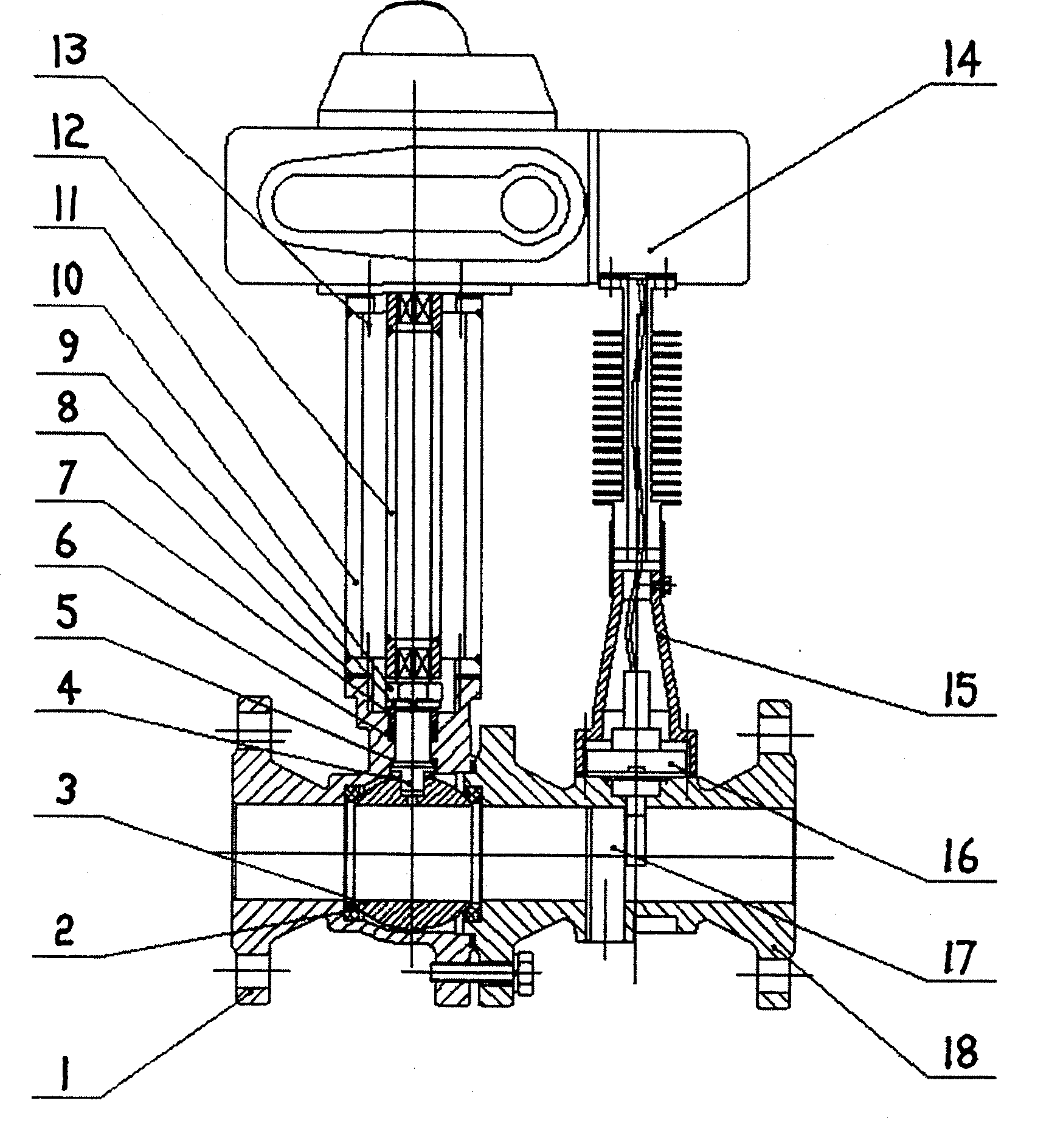
[0013] Such as figure 1 The intelligent control vortex street flow sensor of the present invention is shown, wherein the valve body 1, the ball pad 2, the ball 3, the valve stem 4, the small slice 5, the packing 6, the pressure sleeve 7, the asbestos pad 8, the spring washer 9, and the nut 10 , bracket 11, coupling 12, screw 13, electric actuator 14, radiator, vortex flow sensor 16, triangle body 17 and valve cover 18; among them, between the ball 3 and the valve body 1, between the ball 3 and the valve cover 18 They are respectively sealed by a ball gasket 2; the valve stem 4 is installed in the inverted middle mouth of the valve body 1, and one end is in the groove of the ball 3; the small sheet 5 is installed in the undercut groove of the middle mouth of the valve body 1 , sandwiched between the valve body 1 and the valve stem 4, and act as a seal between the valve stem 4 and the valve body 1; In the upper groove; the nut 10 and the spring washer 9 press the pressure sleev...


PUM


Abstract

The invention relates to an instrument pipeline fluid control device, comprising bracket, shaft coupler, radiator, protective cover, electric actuator, high temperature ball valve and vortex flow sensor, where the casing of the electric actuator is a lengthened casing, the electric actuator is installed through the bracket on an actuator platform of the high temperature ball valve and the shaft coupler connects the electric actuator and high temperature ball valve; circuit board of the vortex flow sensor is directly installed in the lengthened casing, and the protective cover and radiator are arranged between the main body of the vortex flow sensor and the electric actuator; probe signals are transmitted through leads to signal amplification circuit board. And it has advantages of convenient to measure and convenient to control pipeline ON/OFF.

Description

technical field [0001] The invention relates to a fluid control device, more precisely, the invention relates to a fluid control device for an instrument pipeline. It belongs to the field of mechanical technology. Background technique [0002] At present, in the control of any oily or liquid liquid, the fluid pipeline control valve is roughly divided into water control valve, oil control valve, and liquid control valve (that is, chemical solution or any other non-water and non-oil liquid) due to different usability. , all use the opening and closing control of the pipeline channel to complete the water, oil or liquid drainage control. However, these control devices have the following defects in use in the past, that is, they cannot measure the flow of the fluid flowing through the pipeline well, or they cannot help the supply unit to control the amount of fluid well for charge management. It is also very inconvenient to control its switching on or off simultaneously. Con...

Claims


Application Information

Patent Timeline
Patent Type & Authority Patents(China)
IPC IPC(8): G01F1/32G01F15/00
Inventor 孙建荣
Owner NANJING XIAO INSTR MEASUREMENT
Why Eureka
Try Eureka